Adapting the terminal strip
6.5 Analog outputs
Inverter with CU230P-2 Control Units
Operating Instructions, 11/2013, FW V4.6.6, A5E02430659B AG
103
Analog outputs
Changing the function of the analog output
Define the analog output type using
parameter p0776 (e.g. voltage output -
10 V … 10 V or current output
4 mA … 20 mA).
Interconnect parameter p0771 with a
connector output of your choice (e.g. the
actual speed).
In the parameter list of the List Manual,
connector outputs are marked with "CO".
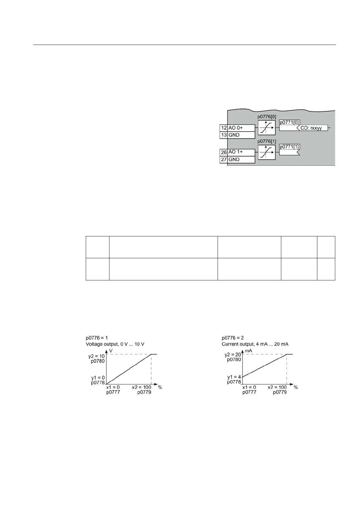
The adjacent figure shows the termi
nals of the
Define the analog output type
The converter offers a series of default settings, which you can select using parameter
p0776:
AO 0
Current output (factory setting)
Voltage output
0 mA … +20 mA
0 V … +10 V
p0776[0] = 0
1
AO 1 Current output (factory setting)
Voltage output
0 mA … +20 mA
0 V … +10 V
p0776[1] = 0
1
Characteristics of the analog output
If you change the analog output type, then the inverter automatically selects the appropriate
scaling of the analog output. The linear scaling characteristic is defined using two points
(p0777, p0778) and (p0779, p0780).
Figure 6-3 Examples for scaling characteristics
Parameters p0777 … p0780 are assigned to an analog output via their index, e.g.
parameters p0777[0] … p0770[0] belong to analog output 0.

 Loading...


