Installing
4.2 Installing reactors, filters and braking resistors
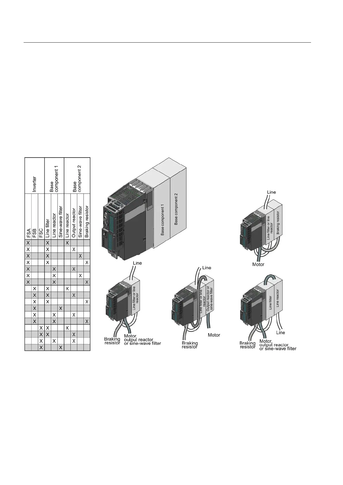
Inverter with CU230P-2 Control Units
42 Operating Instructions, 11/2013, FW V4.6.6, A5E02430659B AG
Installing reactors, filters and braking resistors
Installing reactors, filters and braking resistors
The installation of reactors, filters and braking resistors is described in the documentation
provided. See also Section: Additional information on the inverter (Page 446).
Installing base components
Reactors, filters and braking resistors are available as base components for the PM240 and
PM250 Power Modules, frame sizes FSA, FSB and FSC. You can also install base
components next to Power Modules.
Figure 4-1 Permissible combination of base components
Electrical connections of the line reactor and line filter
● Line connection via terminals
● Inverter connection via a prefabricated cable
Electrical connections of the output reactor and sine-wave filter
● Inverter connection via a prefabricated cable
● Motor connection via terminals

 Loading...


