Setting functions
8.6 Protection functions
Inverter with CU230P-2 Control Units
264 Operating Instructions, 11/2013, FW V4.6.6, A5E02430659B AG
During vector control, the motor current remains within the torque limits set there.
During V/f control, the maximum current controller (I-max controller) protects the motor and
inverter against overload by limiting the output current.
I-max controller operation
If an overload situation occurs, the speed and stator voltage of the motor are reduced until
the current is within the permissible range. If the motor is in regenerative mode, i.e. it is
being driven by the connected machine, the I-max controller increases the speed and stator
voltage of the motor to reduce the current.
Note
The inverter load is only reduced if the motor torque decreases at lower speeds, e.g. for
fans.
In the regenerative mode, the current only decreases if the torque decreases at a higher
speed.
You only have to change the factory settings of the I-max controller if the drive tends to
oscillate when it reaches the current limit or if it is shut down due to overcurrent.
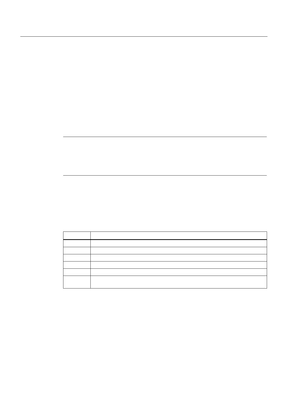
Table 8- 23 I-max controller parameters
Proportional gain of the I-max controller for speed reduction
Integral time of the I-max controller for speed reduction
Status: I-max controller active
r1343
Speed output of the I-max controller
Shows the amount to which the I-max controller reduces the speed.
For more information about this function, see function diagrams 1690 and 6714 in the List
Manual.

 Loading...


