Setting functions
8.3 Setpoints
Inverter with CU230P-2 Control Units
Operating Instructions, 11/2013, FW V4.6.6, A5E02430659B AG
239
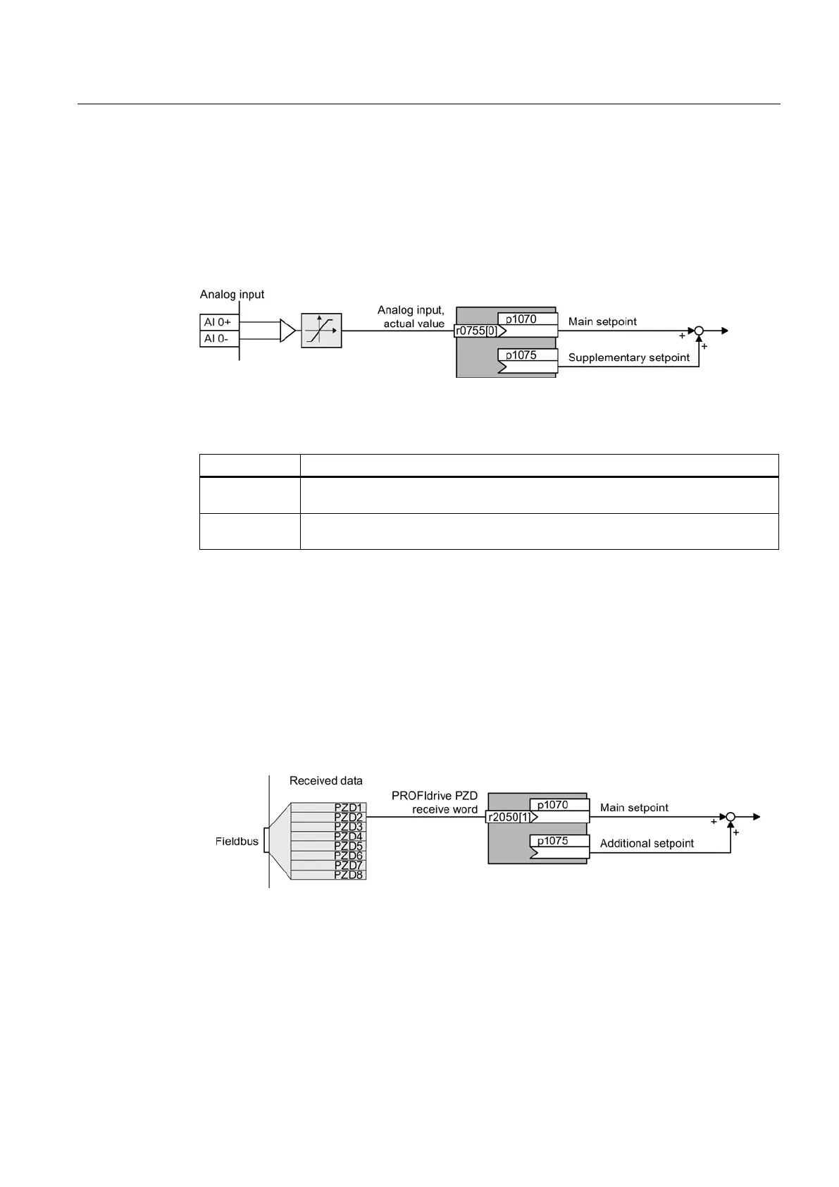
Analog input as setpoint source
Interconnecting an analog input
If you have selected a pre-assignment without a function of the analog input, then you must
interconnect the parameter of the main setpoint with an analog input.
Figure 8-12 Example: Analog input 0 as setpoint source
Table 8- 7 Setting with analog input 0 as setpoint source
p1070 = 755[0]
Interconnect the main setpoint with analog input 0
p1075 = 755[0]
Interconnect the additional setpoint with analog input 0
You must adapt the analog input to the connected signal, e.g. ± 10 V or 4 … 20 mA. You will
find additional information in the section: Analog inputs (Page 98).
Specifying the motor speed via the fieldbus
If you enter the setpoint via a fieldbus, you must connect the converter to a higher-level
control. For further information, see Section Configuring the fieldbus (Page 107).
Interconnecting the fieldbus with the main setpoint
Figure 8-13 Fieldbus as setpoint source
Most standard telegrams receive the speed setpoint as a second process data PZD2.

 Loading...


