08/2005 Commissioning HMI Advanced (IM4)
2 Setting Functions and Parameters
© Siemens AG, 2005. All rights reserved
SINUMERIK 840D sl/840D/840Di/810D Installation and Start-Up HMI (IAM) - 08/2005 Edition
IM4/2-43
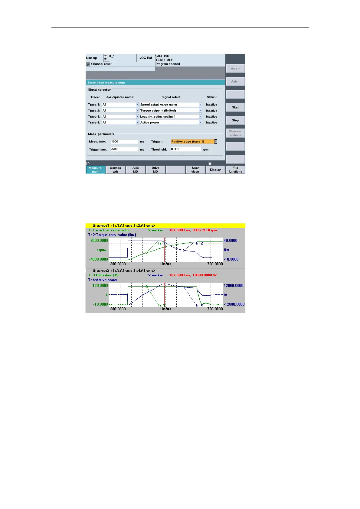
Figure 2-7 Servo trace main screen
Select the variables to be measured from the drop-down list in the “Signal
selection” area. Refer to the motor data sheet to obtain the settings for the
measuring period and trigger time. After parameterization, start the measurement
by pressing the "Start” softkey.
Figure 2-8 Servo trace graphic
Select the constant power range or constant torque range in order to calculate the
normalization factor using these data. For example, in Figure 2-8 the measured
power is 10.5 kW.
If the utilization display is to indicate 100% for nominal data and higher values at
operation above the nominal working point, the normalization factor setting can be
calculated from the motor data or from the diagram and measurement as follows:
$MM_MA_SPIND_MAX_POWER = Maximum_measured_power /
Rated_power_S1 * 100
$MM_MA_SPIND_MAX_POWER = 10500W / 7000W * 100.0 = 150
Enter the factor “150” in the machine data.

 Loading...


