RM0453 Rev 2 847/1454
RM0453 General-purpose timer (TIM2)
893
cleared by an external event through the ETR signal until the next PWM period), the
OCREF signal is asserted only:
• When the result of the comparison or
• When the output compare mode (OCxM bits in TIMx_CCMRx register) switches from
the “frozen” configuration (no comparison, OCxM=‘000) to one of the PWM modes
(OCxM=‘110 or ‘111).
This forces the PWM by software while the timer is running.
The timer is able to generate PWM in edge-aligned mode or center-aligned mode
depending on the CMS bits in the TIMx_CR1 register.
PWM edge-aligned mode
Upcounting configuration
Upcounting is active when the DIR bit in the TIMx_CR1 register is low. Refer to Upcounting
mode on page 827.
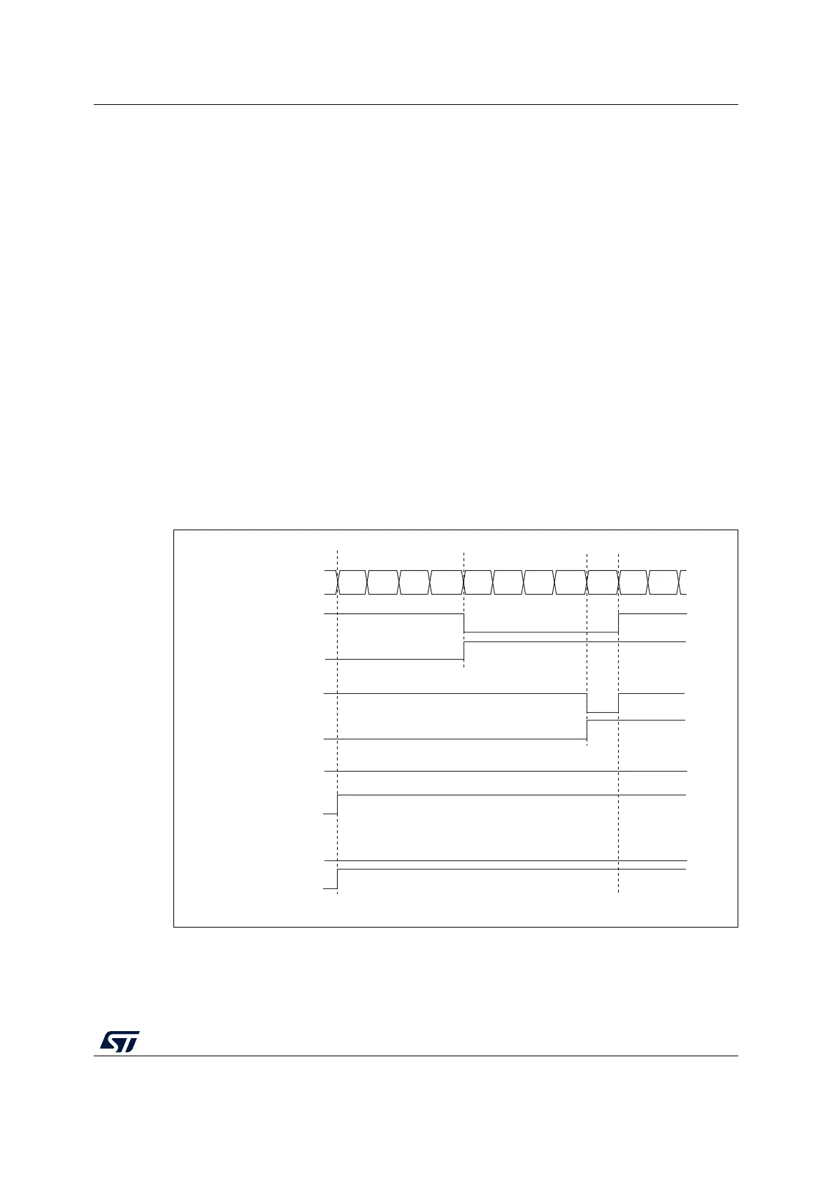
In the following example, we consider PWM mode 1. The reference PWM signal OCxREF is
high as long as TIMx_CNT <TIMx_CCRx else it becomes low. If the compare value in
TIMx_CCRx is greater than the auto-reload value (in TIMx_ARR) then OCxREF is held at ‘1.
If the compare value is 0 then OCxREF is held at ‘0. Figure 218 shows some edge-aligned
PWM waveforms in an example where TIMx_ARR=8.
Figure 218. Edge-aligned PWM waveforms (ARR=8)
MS31093V1
Counter register
‘1’
0
12 3456 7801
OCXREF
CCxIF
OCXREF
CCxIF
OCXREF
CCxIF
OCXREF
CCxIF
CCRx=4
CCRx=8
CCRx>8
CCRx=0
‘0’

 Loading...


