Description Of Specific Functions 113
V560 Series High Performance Closed-Loop Vector Inverter User Manual
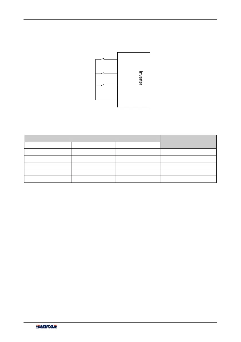
frequency set value of the inverter is shown in Figure 7-2.
Preconditions for below instruction: multifunctional terminal DI1 frequency or process PID setting UP function
([F3.0.00]=15), DI2 sets frequency or process PID DW function ([F3.0.01]=16), and DI5 sets UP/DW with
frequency clear function ([F3.0.04]=17).
UP switch
DOWN switch
DI1
DI2
DI5
COM
Clear switch
Table 7-2 External Switch Status and Current Frequency Set Value of the Inverter
Terminal Status
Set frequency
DI5 DI2
DI1
OFF OFF
OFF
Maintained
OFF OFF
ON
Increased
OFF ON
OFF
Deceased
OFF ON
ON
Maintained
ON Any
Any
Zero
5: Remote UP/DW 2 (go to zero when stopped)
Similar to the case of “4” as above, the inverter will automatically clear current set value after stop.
6: Remote UP/DW 3 (keep value at power-off)
Similar to the case of “4” as above, the set value will be saved automatically after power-off, and the initial set
data will be the set value at the last power-off when the inverter is powered on once again.
7: Remote UP/DW bipolar setting 1 (keep bipolar when stopped)
The basic operation is slimier to that as stated in "the" and the difference is that: in the mode of “4”, the set
frequency is unsigned values (not containing direction information), and the setting range of the frequency is:
0~upper limiting frequency; while in the mode of “7”, the set frequency is signed values (containing direction
changing information), and the setting range of the frequency is: - upper limiting frequency upper limiting
frequency.
The inverter’s actual running direction is according to “XOR” calculation of the command direction (FWD,
REV) and the set frequency direction.
8: Remote UP/DW bipolar setting 2 (keep at power-off)
The basic operation is similar to the case of “7” as above. The set value will be saved automatically after
power-off, and the initial set data will be the set value at the last power-off when the inverter is powered on
once again.
9: Analog input Al1
The frequency set value is given via the analog input AI1; For relevant characteristics please see the
instructions of the parameters F4.0.00 and F4.0.01.
Figure 7-12 Terminal UP/DW wiring sketch
 Loading...
