Functional Parameter Table
V560 Series High Performance Closed-Loop Vector Inverter User Manual
82
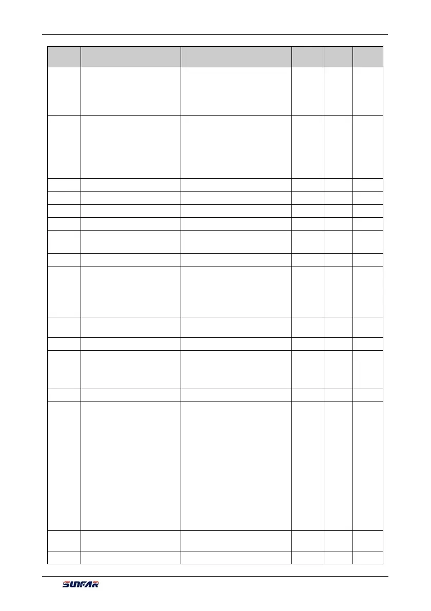
Function
Code
Name Setting Range and Description
Minimum
Unit
Factory
Default
Change
Limit
2: External terminal selection
(Function No.69)
_ _ X _: Action mode
0: Common mode
1: Spindle orientation
Fb.2.24
Position setting source in
common mode
0: Reserved
1: Fin input
2: Digital setting
3: Analog inputAI1
4: MODBUS bus set value 1
5: MODBUS bus set value 2
1 1
Fb.2.25 Position digital setting (lower) 0~65535 1 0
Fb.2.26 Position digital setting (upper) 0~500 1 0
Fb.2.27 Electronic gear (numerator) 0~65535 1 1000
Fb.2.28 Electronic gear (denominator) 0~65535 1 1000
Fb.2.29
Position command filtering time
coefficient
1~1000.0ms 1 10
Fb.2.30 Position gain 2 0.01~100.00 0.01 1.00
Fb.2.31 Position gain selection
0: Gain 1 Effective
1: Gain 2 Effective
2: External terminal selection
(Function No. 75)
3: Position deviation selection
1 0
Fb.2.32
Position gain selected threshold
value (Position deviation)
0~30000 1 10
Fb.2.33 Speed feed-FWD gain 0.0~200.0 (%) 0.1 100.0
Fb.2.34
Rotate speed regulating in
common servo mode
0: Limit by the upper frequency
1: Minimax between the frequency
set channel and position loop
control
1 0
Fb.2.35 —— ——
Fb.2.36 Spindle orientation mode
_ _ _ X: Selection of
reference signal for
positioning zero point
0: Z pulse positioning
1: Photoelectric switch
positioning(Function No. 70)
_ _ X _: Command
0: External terminal selection
1: Pulse command setting(Fin)
_ X _ _: Direction arrival
0: Locate according to the order
1: Locate according to the minimum
corner
1 0000 ×
Fb.2.37
Spindle orientation frequency/
speed
0.01~100.00Hz 0.01 5.00
Fb.2.38 Spindle orientation angle 1 0~359.9 0.1 45.0