the 2
nd
profile settings for the 2
nd
channel, defined
in the case of SLM mode - in Table B.1.5_SLM and
in the case of VLM mode - in Table B.1.5_VLM
the 2
nd
profile settings for the 3
rd
channel, defined
in the case of SLM mode - in Table B.1.5_SLM and
in the case of VLM mode - in Table B.1.5_VLM
the 2
nd
profile settings for the 4
th
channel, defined
in the case of SLM mode - in Table B.1.5_SLM and
in the case of VLM mode - in Table B.1.5_VLM
the 3
rd
profile settings for the 1
st
channel, defined
in the case of SLM mode - in Table B.1.5_SLM and
in the case of VLM mode - in Table B.1.5_VLM
the 3
rd
profile settings for the 2
nd
channel, defined
in the case of SLM mode - in Table B.1.5_SLM and
in the case of VLM mode - in Table B.1.5_VLM
the 3
rd
profile settings for the 3
rd
channel, defined
in the case of SLM mode - in Table B.1.5_SLM and
in the case of VLM mode - in Table B.1.5_VLM
the 3
rd
profile settings for the 4
th
channel, defined
in the case of SLM mode - in Table B.1.5_SLM and
in the case of VLM mode - in Table B.1.5_VLM
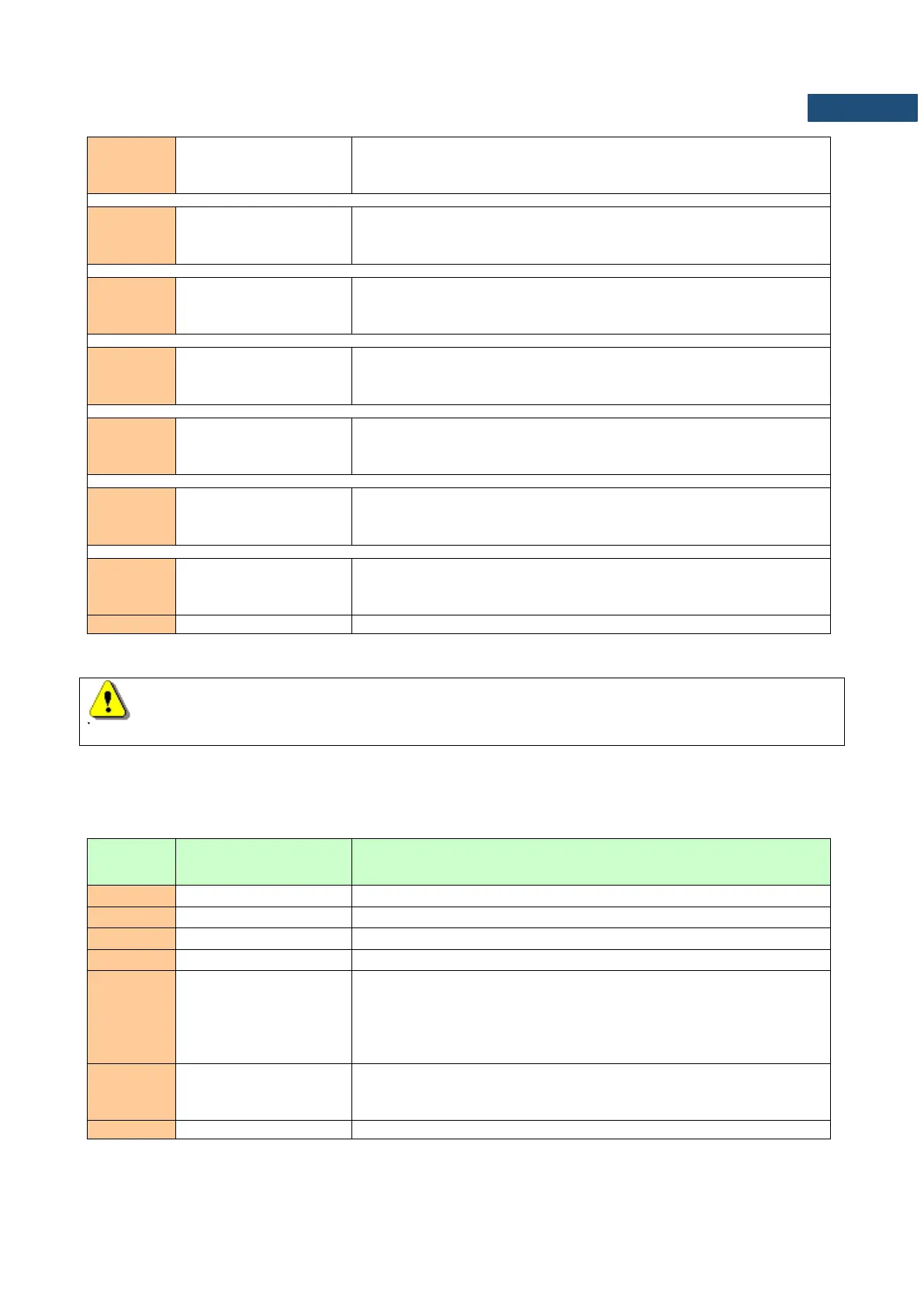
Note: In RT60 measurements mode the whole block exists but the values in that table have no
interpretation (they are meaningless).
Table B.1.5_SLM. Software settings for a channel in the case of SLM mode
number of channel: 0 - first channel
filter type in the channel: 1 - LIN, 2 - A, 3 - C, 4 = G
detector type in the channel: 0 - IMP., 1 - FAST, 2 - SLOW
logger contents in the channel defined as a sum of :
1 - for PEAK results,
2 - for MAX results,
4 - for MIN results,
8 - for RMS results,
flags word (16 bits): b15 ... b3 b2 b1 b0
b0 - if set to 1: profile results have been calculated
b1 ... b15 - reserved