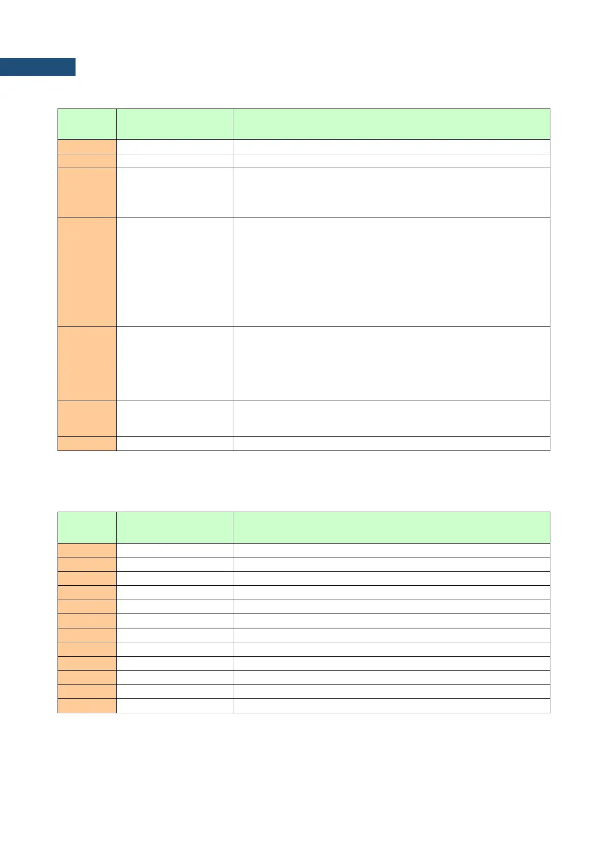
Table B.1.5_VLM. Software settings for a channel in the case of VLM mode
[08, nn=sub-block_length]
channel number: 0 - the 1
st
channel
filter type in the channel: 1 - HP1, 2 - HP3, 3 - HP10, 4 - Vel1,
5 - Vel3, 6 - Vel10, 7 - VelMF, 8 - Dil1, 9 - Dil3, 10 - Dil10,
15 - KB, 16 - Wk, 17 - Wd, 18 - Wc, 19 - Wj, 20 - Wm, 21 - Wh,
22 - Wg, 23 - Wb, 25 - Wv, 28 - Wz
detector type in the channel:
0 - 100 ms,
1 - 125 ms,
2 - 200 ms,
3 - 500 ms,
4 - 1 s,
5 - 2 s,
6 - 5 s,
7 - 10 s
logger contents in the channel defined as a sum of:
1 - for PEAK results,
2 - for P–P results,
4 - for MAX results,
8 - for RMS results,
16 - for VDV results
flags word (16 bits): b15 ... b3 b2 b1 b0
b0 - if set to 1: profile results have been calculated
b1 ... b15 - reserved
Table B.1.6. Vector measurement settings
[1E, nn=sub-block_length]
vector result logging: 0 - OFF, 1 – ON
vector coefficient for the 1
st
channel (*100)
vector coefficient for the 2
nd
channel (*100)
vector coefficient for the 3
rd
channel (*100)
vector coefficient for the 4
th
channel (*100)
1
st
channel used for calculation: 0 - no, 1 - yes
2
nd
channel used for calculation: 0 - no, 1 - yes
3
rd
channel used for calculation: 0 - no, 1 - yes
4
th
channel used for calculation: 0 - no, 1 - yes
VECTOR result value (*100 dB)