SECTION 6 ERROR MESSAGE
SERIES
Sysmex
CA-500
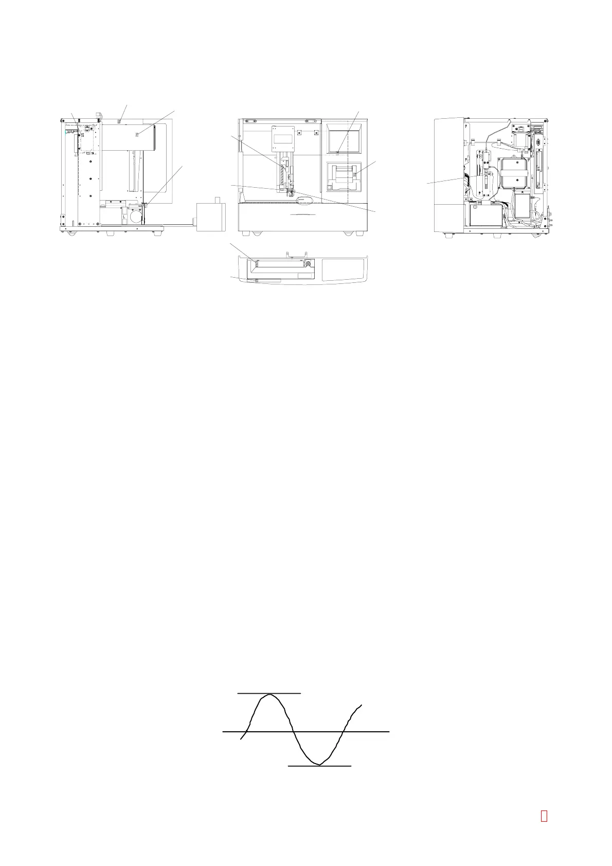
Cover Sensor
Barcode Reader
Home Position Sensor
Sampler Cover
Open Sensor
Z Axis Home
Position Sensor
Tube
Detection
Sensor
Liquid Serface
Sensor
Pipette Crash
Sensor
Paper Empty
Sensor
Y Axis Home
Position Sensor
X Axis Home
Position Sensor
STAT
Rack Detection Sensor
H
O
S
T
Syringe
Home Position
Sensor
Figure 6-1: Sensor Positions
6.1 PRESSURE ERRORS
6.1.1 Pressure Pump Error
Monitor Timing: At time of each analysis start and/on rinse start, just before opening SV
Monitor Method: Monitoring 225 g/cm
2
r 10% by the comparator
CA-500’s Action: Emergency stop
(1) Probable Cause
1. The rinse bottle is not connected.
2. The cap of rinse bottle is removed.
3. SV failure
4. Pressure pump failure
5. Perforations (pinhole) in the hydraulic line.
6. Pressure sensor failure
7. Sensor circuit failure
8. Drive circuit failure
(2) Confirmation by the Operator
1. Properly connect the tube.
2. Securely tighten the bottle cap.
(3) Confirmation by the Service Engineer
1. When SV is faulty, rinse solution keeps flowing out from sample probe or rinse cup. Replace faulty SV.
2. When the hydraulic line has no failure, the pressure pump or related electronic circuit has a trouble.
If replacement of the pressure pump allows the pressure adjustment, the pressure pump is failed; if not,
the electronic circuit is failed.
3. The pressure pump turn ON or OFF at the pressure 250 g/cm
2
. If the pump does not start operating
even when the cap of rinse bottle is removed, the pump or its drive circuit is failed.
Measure voltage at the connector of pump by the DVM. If AC 100 V ± 15% is displayed, the pump is
failed; if not, the drive circuit is failed.
141V peak
-141V peak
Figure 6-1-1: Normal Oscilloscope Wave
CA-500 Series S/M 6-1 Revised December 2001 8