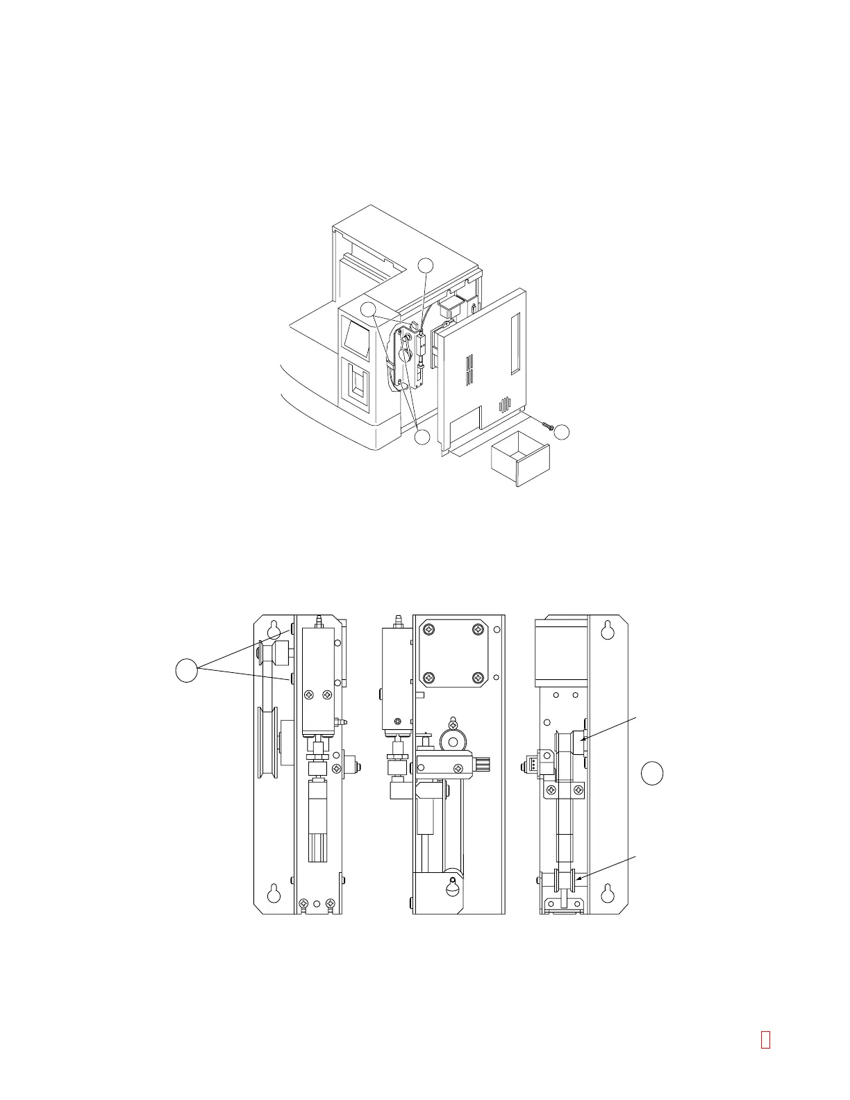
C.3 Volumetric Unit Assembly
(1) Remove Right Side Panel by removing two screws.
(2) Disconnect Photo Sensor connector and Motor connector.
(3) Move the pipette to Rinse Cup and disconnect the tubing.
(4) Remove the volumetric unit motor by loosening two screws (item 4).
1
2
3
4
Figure C-4: Removing Volumetric Unit Motor
(5) The motor is fixed by two fixing screws (item 5). (Adjust the belt tension so that the belt is indented 4 mm
when it is pushed at the center by a finger.)
(6) As for the adjustment of the tension between Idler and Pulley, adjust it at Pulley position. (Adjust the belt
tension so that the belt is indented 4 mm when it is pushed at the center by a finger.)
6
5
Pulley
Idler
Figure C-5: Adjusting Belt Tension
8 CA-500 Series S/M C-4 Revised December 2001