SECTION 3 ELECTRONICS
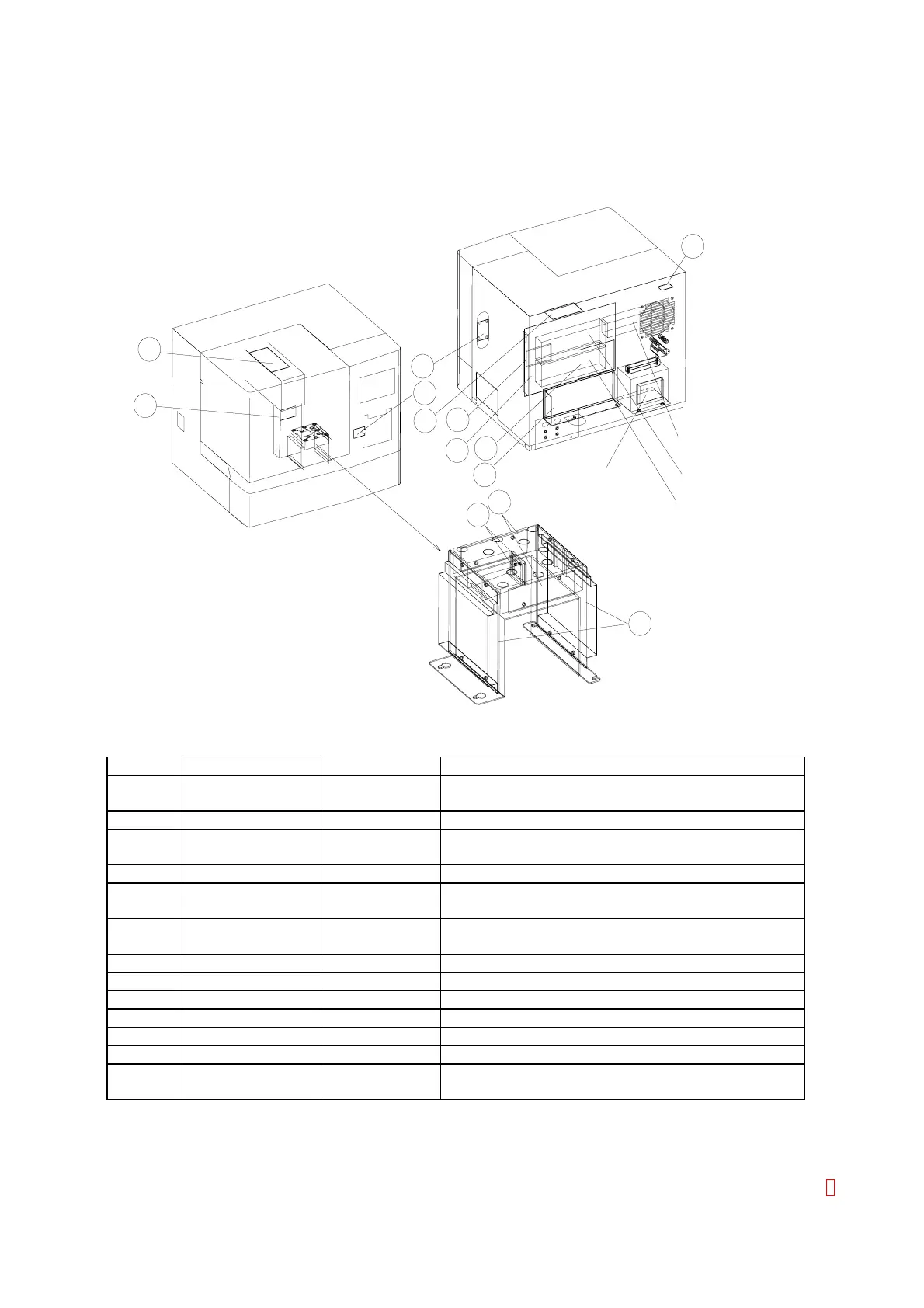
3.1 PCB Locations
Switching Regulator
Transformer
9
4
6
5
3
LCA150S-24-XJCM
LCA150S-12
LCA50S-5
7
10
11
8
12
1
13
2
Figure 3-1: PCB Location
Symbol Description Name Functions
1 PCB No. 2132
PCB No. 2156*
PD
PD2
Photo Diode LED, Pre-Amplifier
2 PCB No. 2133 THERMO Thermister (for Room Temperature)
3 PCB No. 2134
PCB No. 2157*
Y-Z RELAY
Y-Z RELAY2
Liquid Surface Sensor, Probe Crash,
Y-Axis Home Position Sensor
4 PCB No. 4086 PS Power Supply, Motor Drive
5 PCB No. 6350
PCB No. 6375*
PRCN-1
PRCN-3
Printer Control Board
6 PCB No. 6362
PCB No. 6373*
MAIN
MAIN-2
CPU, I/O, Motor Control, Temperature Control, A/D
7 PCB No. 7015 MEMORY Program Memory
8 PCB N0. 9258 LED2 LED (for analyzing scattered light)
9 PCB No. 9259 LED1 LED (for analyzing transmitted light)
10 PCB No. 9260 X RELAY X-Axis Relay
11 PCB No. 9263 VR LCD Contrast Volume
12 PCB No. 9264 Z RELAY Z-Axis Relay, Z-Axis Home Position Sensor
13 PCB No. 9265
PCB No. 9303*
PR RELAY
PR RELAY2
Operation Panel, Syringe Motor, SV Relay
NOTE: PCB No. indicated with (*) is added with CA-550/560 which is upper compatible.
CA-500 Series S/M 3-1 Revised December 2001 8