6.9.2 Printer Error
Monitor Timing: At time of printing
Monitor Method: Monitoring head up signal of Printer
CA-500’s Action: Warning and no printing
(1) Probable Cause
1. The head up lever is not set down.
2. Failure of Printer
3. Failure of PCB No. 9265
4. Failure of wiring cord (for printer relaying)
5. Failure of PCB No. 6350
(2) Confirmation by the operator
1. Place printer paper correctly.
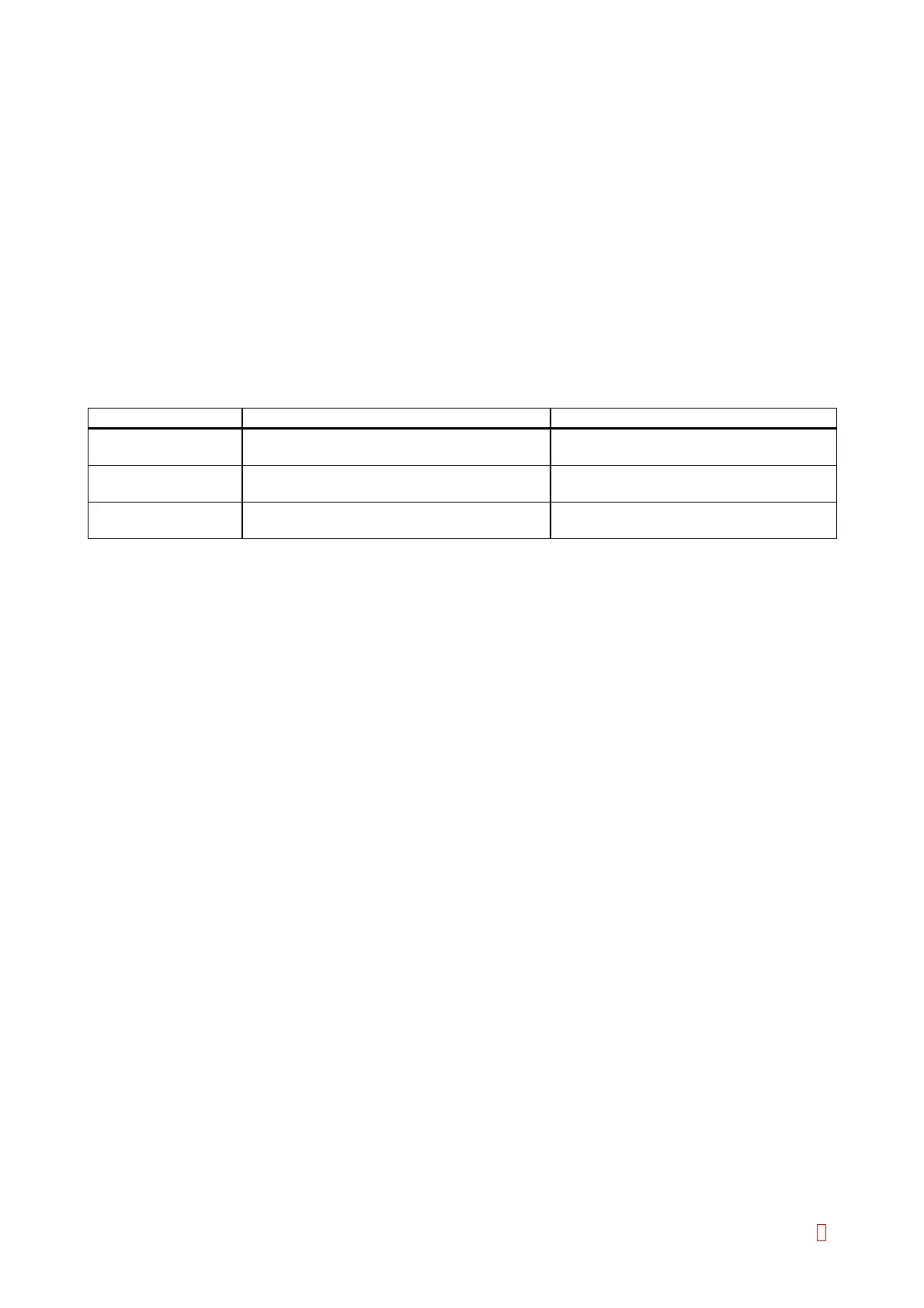
(3) Confirmation by Service Engineer
Suspect Part Test Points Expected Value
Printer CN3 (PCB No. 9265) pin 2 and pin 1 5 V Æ 0 V
when pulling the lock lever down
PCB No. 9265 CN1 (PCB No. 9265) pin 3 and pin 4 5 V Æ 0 V
when pulling the lock lever down
Wiring Cord
(for printer relaying)
CN4 (PCB No. 6350) pin 1 and pin 2 5 V Æ 0 V
when pulling the lock lever down
6.9.3 HC Off Line
Monitor Timing: When communicating with host computer
Monitor Method: Monitoring RS-232C DSR control signal
CA-500’s Action: Warning
(1) Probable Cause
1. The connector cable is disconnected.
2. The host computer is not turned on.
3. The host computer is not ready to receive data.
4. Failure of PCB No. 6362
(2) Confirmation by the operator
1. Check the connection with host computer.
2. Turn on the host computer.
3. Check the host computer data transmission.
(3) Confirmation by Service Engineer
1. Replace the PCB No. 6362.
CA-500 Series S/M 6-31 Revised December 2001 8