6.5.4 No Reaction Tube
Monitor Timing: Just after the catching operation at reaction tube rack
Monitor Method: Tube detection sensor monitors a reaction tube.
CA-500’s Action: Interruption
(1) Probable Cause
1. A reaction tube cannot be caught.
2. Tube catch operation is obstructed.
3. The catcher tried to catch a reaction tube from the middle of tube rack, but it failed.
4. No tube
5. The number of tube rack exceeds 60 during analysis.
6. The catcher is too dirty to function.
7. Mis-positioned tube
8. Failure of catcher
9. Dirty of tube detection sensor
10. Failure of tube detection sensor
11. Failure of PCB No. 9264
12. Failure of PCB No. 2134
13. Failure of Y-Z relay harness
14. Failure of PCB No. 9260
15. Failure of X axis wiring cord
16. Failure of wiring cord (flat cable)
17. Failure of PCB No. 6362
(2) Confirmation by the operator
1. Remove reaction tubes that are standing in the way.
2. Remove anything that is obstructing the catching operation.
3. Clean any contamination by alcohol or the like.
4. Place the tubes in order.
5. Place the tubes properly in the quantity required for testing.
* If sample discharged in the tube rack or on the reagent stage, clean them.
(3) Confirmation by Service Engineer
1. When catching error has occurred,
a) Correct any mis-positioning.
b) Replace the catcher.
2. When an error occurs though a tube is caught:
a) If the tube detection sensor is dirt, wipe it clean by alcohol.
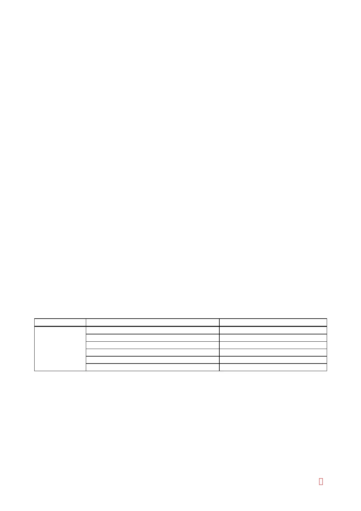
Suspect Part Test Points Expected Value
Tube Detection CN2 (PCB No. 9264) pin 3 (GND) and pin 2 5 V Æ 0 V when a tube is detected
Sensor CN1 (PCB No. 9264) pin 13 (GND) and pin 8 5 V Æ 0 V when a tube is detected
CN4 (PCB No. 2134) pin 13 (GND) and pin 8 5 V Æ 0 V when a tube is detected
CN1 (PCB No. 2134) pin 16 (GND) and pin 4 5 V Æ 0 V when a tube is detected
CN1 (PCB No. 9260) pin 16 (GND) and pin 4 5 V Æ 0 V when a tube is detected
CN105 (PCB No. 6362) pin 13 (GND) and pin 1 5 V Æ 0 V when a tube is detected
CA-500 Series S/M 6-17 Revised December 2001 8