3.11 PCB No. 9259 (LED1; LED for transmitted light)
3.11.1 Function
This PC Board is the board for mounting the LED for the transmitted light in the Detector Block. This LED
is driven in the constant current driving circuit (20 mA) on PCB No. 6362 (MAIN) or PCB No. 6373 (MAIN-
2) together with the LED for the scattered light.
3.11.2 Setting and Adjustment
Setting and adjustments are not necessary.
3.11.3 LED and Test Point
There are no LEDs or test point.
3.12 PCB No. 9260 (X RELAY; X-Axis Relay)
3.12.1 Function
This PCB is used for the signal relay and the X-Axis Home Position Sensor signal relay to PCB No.
2134 (Y-Z RELAY) via FFC (Flexible Flat Cable).
3.12.2 Block Diagram
PCB No.6362(MAIN)
PCB No.6373(MAIN-2)
PCB No.4086(PS)
X-Axis Home Position Sensor
to PCB No. 2134 (Y-Z RELAY)
to PCB No. 2157 (Y-Z RELAY2)
Signal Relay
Signal Relay
Figure 3-16: PCB No. 9260 Block Diagram
3.12.3 Settings and Adjustment
Setting and adjustments are not necessary.
3.12.4 LED and Test Point
There are no LEDs or test point.
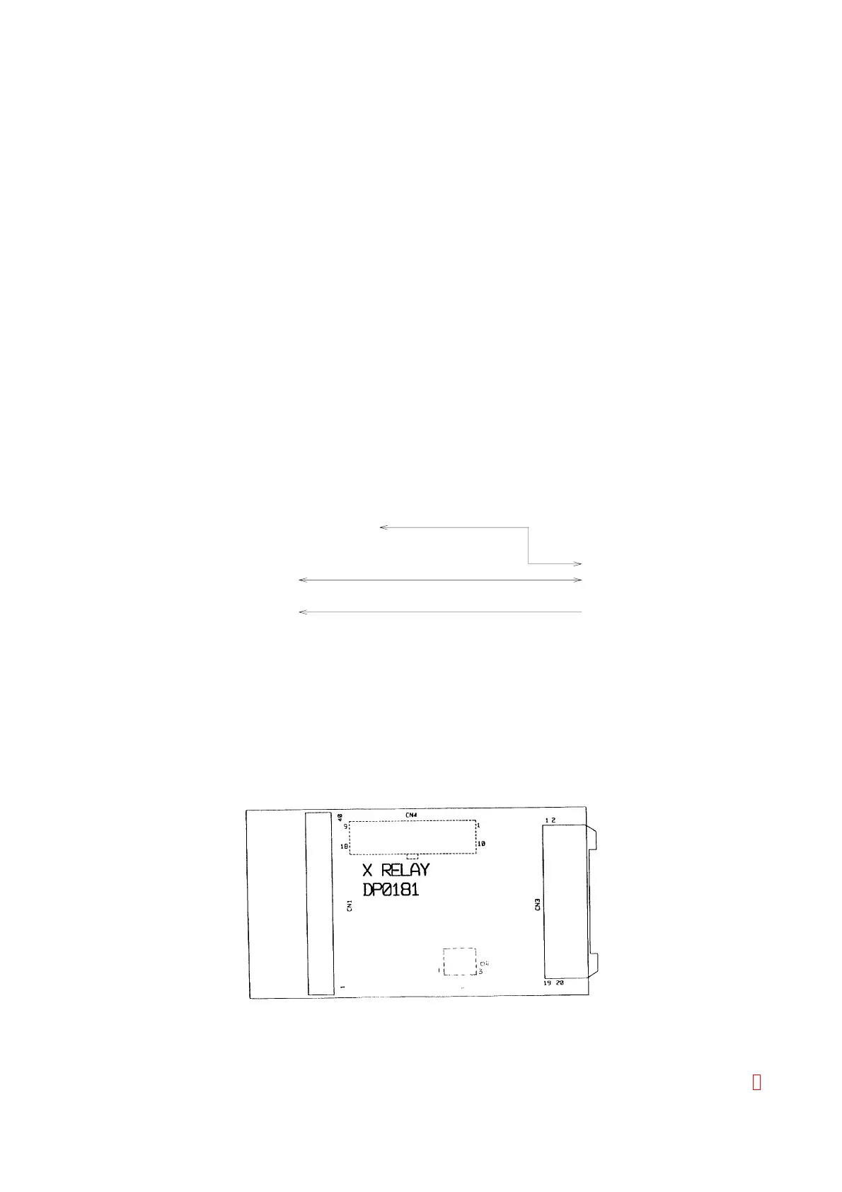
3.12.5 Assembly Drawing
Figure 3-17: PCB No. 9260 Assembly Drawing
CA-500 Series S/M 3-24 Revised December 2001 8