6.4.5 Tube Catch Error (Position)
Monitor Timing: Just after the reaction tube catching operation
Monitor Method: Tube detection sensor monitors the Tube catch error.
CA-500’s Action: Interruption
(1) Probable Cause
1. A tube cannot be caught.
2. Tube catch operation is obstructed.
3. Tube catcher tried to catch a reaction tube not in the order.
4. The catcher is too dirty to function.
5. Mis-positioned catcher
6. Defective catcher
7. Tube detection sensor is dirty.
8. Failure of tube detection sensor
9. Failure of PCB No. 9264
10. Failure of PCB No. 2134
11. Failure of PCB No. 9260
12. Failure of X axis wiring cord
13. Failure of PCB No. 6362
(2) Confirmation by the Operator
1. Remove anything that is obstructing the catching.
2. Clean any contamination using alcohol or the like.
(3) Confirmation by Service Engineer
1. When Tube Catch Error has occurred,
a) Correct any mis-positioning that has happened.
b) Replace the catcher.
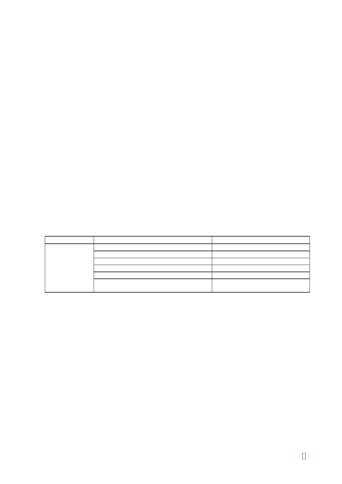
2. When an error occurs though a tube is caught:
Suspect Part Test Points Expected Value
Tube Detection CN2 (PCB No. 9264) pin 3 (GND) and pin 2 5 V Æ 0 V when a tube is detected
Sensor CN1 (PCB No. 9264) pin 13 (GND) and pin 8 5 V Æ 0 V when a tube is detected
CN4 (PCB No. 2134) pin 13 (GND) and pin 8 5 V Æ 0 V when a tube is detected
CN1 (PCB No. 2134) pin 16 (GND) and pin 4 5 V Æ 0 V when a tube is detected
CN1 (PCB No. 9260) pin 16 (GND) and pin 4 5 V Æ 0 V when a tube is detected
CN105 (PCB No. 6362) pin 13 (GND) and
pin 1
5 V Æ 0 V when a tube is detected
CA-500 Series S/M 6-12 Revised December 2001 8