CA-500 Series S/M 4-11 Revised December 2001
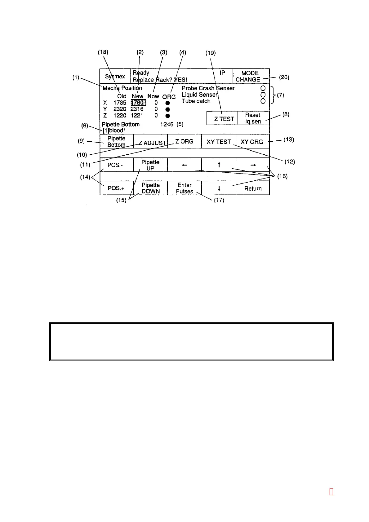
4.3.3 The Mechanical System Position Adjustment Screen
Figure 4-3-1: Mecha Position Screen
(1) Indicating the title of displayed screen.
(2) Display setting values, which indicate number of pulses of moved probe.
The probe moves to these setting values by pressing “XY TEST” and “Z ADJUST” keys.
(3) Display pulses of the probe position.
Moves to these setting values by pressing “XY TEST” and “Z ADJUST” keys.
(4) Display status of the sensor at the home position on each XYZ drive axis:
Black Circle Æ Detected (Activated), White Circle Æ Not Detected (Not Activated)
(5) Display pipette lower limit.
Usually, it is automatically set 25 pulses added to Z position adjustment value.
(6) Display selected setting position.
(Normal: Fine Adjustment Mode/Reverse: Basic Position Adjustment Mode.)
(7) Display status of each sensor on the probe:
Black Circle Æ Detected (Activated), White Circle Æ Not Detected (Not Activated)
REFERENCE: The reaction tube, held by the catcher, is detected by the reflection sensor at the
detection position. When Z is at the home position, the black circle will be displayed
because usually the sensor is in front of the catcher.
(8) [Reset Liq. Sen]Key: Reset the detecting status of the liquid surface sensor.
(9) [Pipette Bottom], [Tube Free], [Tube Catch] Keys: Change depending to the setting position.
• Pipette Adjustment: [Pipette Bottom]
• Catcher Adjustment: [Tube Free] ÅÆ [Tube Catch]
(10) [Z ADJUST] Key: Move the pipette or the catcher according to the setting pulses.
(11) [Z ORG] Key: Return the pipette or the catcher to Z home position.
(12) [XY TEST] Key: Move XY drive according to the setting pulses.
When the probe is not at the home position, it will move to the setting value after returning to the home
position.
8