CA-500 Series S/M 3-6 Revised December 2001
8
3.3 PCB No. 2132 (PD; Photo Diode, Pre-Amplifier, LED Relay)
PCB No. 2156 (PD2; Photo Diode, Pre-Amplifier, LED Relay)
3.3.1 Function
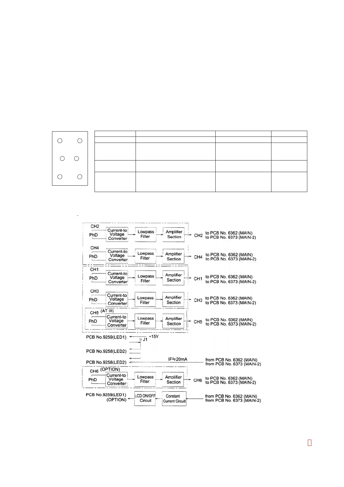
These PC Boards amplify the detector signal in channels CH1~CH6 and drives LEDs for these channels.
There are four kinds of boards (for CH2, 4, 6, for CH1, 3, 5, for CH1, 3, and for CH2, 4). Actually, this
board is used with composing two kinds of the board. (Refer to the table below.)
This circuit detects the scattered light on the channels CH1~CH4, the transmitted light on the channel CH5
on Detector Block (ATIII) and the transmitted light on the channel CH6 on Detector Block (Immunoassy),
amplifies by the current/voltage converter, and output to PCB No. 6362 (MAIN) or PCB No. 6373 (MAIN-2).
CH to be Used PCB No. Model Part No.
2,4,6 PCB No. 2156 (Immuno) CA-550/560 662-0285-7
2,4 PCB No. 2132 (Standard)
PCB No. 2156 (Standard
Coag/Chrom)
CA-510/520/530/540 662-0217-3
662-0281-2
1,3 PCB No. 2132 (2 Circuits)
PCB No. 2156 (2 Circuits Coag)
CA-510/521 662-0218-7
662-0282-6
CH2 CH1
CH6 CH5
CH4 CH3
<Detector Block>
1,3,5 PCB No. 2132 (3 Circuits)
PCB No. 2156 (3 Circuits
Chrom/Immuno)
CA-530/540/550/560 662-0219-1
662-0283-0
3.3.2 Block Diagram
Figure 3-4:
PCB No. 2132 and 2156 Block Diagram