6.2.2 Temperature Error (High)/Detector, Temperature Error (Low)/Detector
Monitor Timing: When READY: 1-minute interval
During analysis: At time of detection start
Monitor Method: A/D converter reads the thermal sensor data embedded in the sample probe as follows:
Room temperature less than 30qC: Temperature error when exceeds the range 36.0 -
38.0qC.
Room temperature above 30qC: Temperature error when exceeds the range 36.0 -
40.0qC.
(1) Probable Cause
1. Room temperature became outside the range between 15 - 35qC.
2. Check whether any obstacle is in front of the ventilation fan, or the ventilator is too close to the wall.
3. Failure of temperature sensor
4. Heater failure
5. Failure of PCB No. 6362
6. Failure of PCB No. 4086
7. Failure of main unit fan
(2) Confirmation by the Operator
1. Confirm room temperature by checking temperature displayed on the main unit.
2. Provide sufficient space around the ventilator.
(3) Confirmation by Service Engineer
1. Check the main unit fan is operating or not. If not, inside temperature rises, causing it impossible to
keep the detector at 37qC.
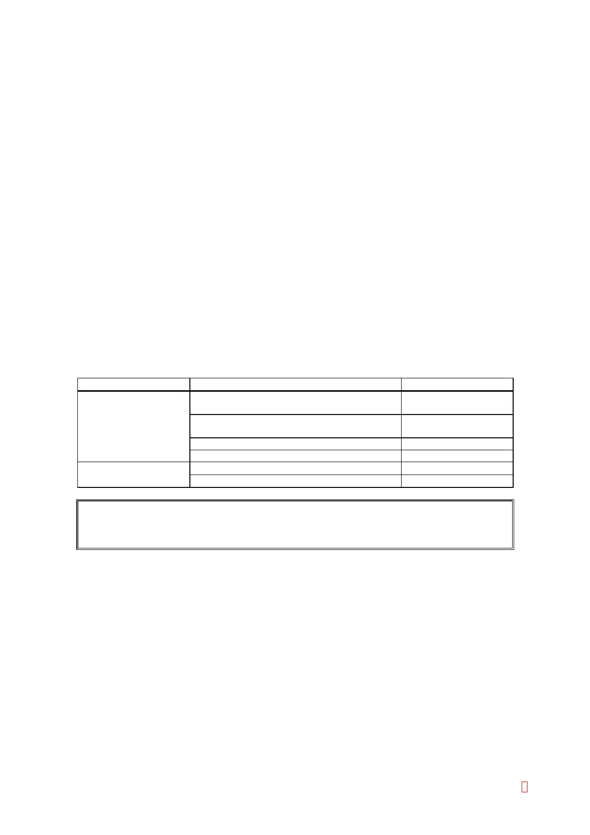
Suspect Part Test Points Expected Value
Temperature sensor Temperature sensor connector pin 1 (green)
and pin 3 (black) (GND)
+5 V
Temperature sensor connector pin 2 (white)
and pin 3 (black) (GND)
0.35 V to 0.39 V
CN115 (PCB No. 6362) pin 4 and pin 6 (GND) +5 V
CN115 (PCB No. 6362) pin 5 and pin 6 (GND) 0.35 V to 0.39 V
Heater Heater connector pin 1 and pin 2
below 3 : or over 7 :
CN8 (PCB No. 4086) pin 1 and pin 5
below 3 : or over 7 :
NOTE: Use high input impedance device. Usually normal Digital Volt Meter input impedance
is higher than 1 Mega : and Oscilloscope is higher than 10 Mega :.
CA-500 Series S/M 6-4 Revised December 2001 8