C.5 Operation Panel Assembly
(1) Remove all the panels.
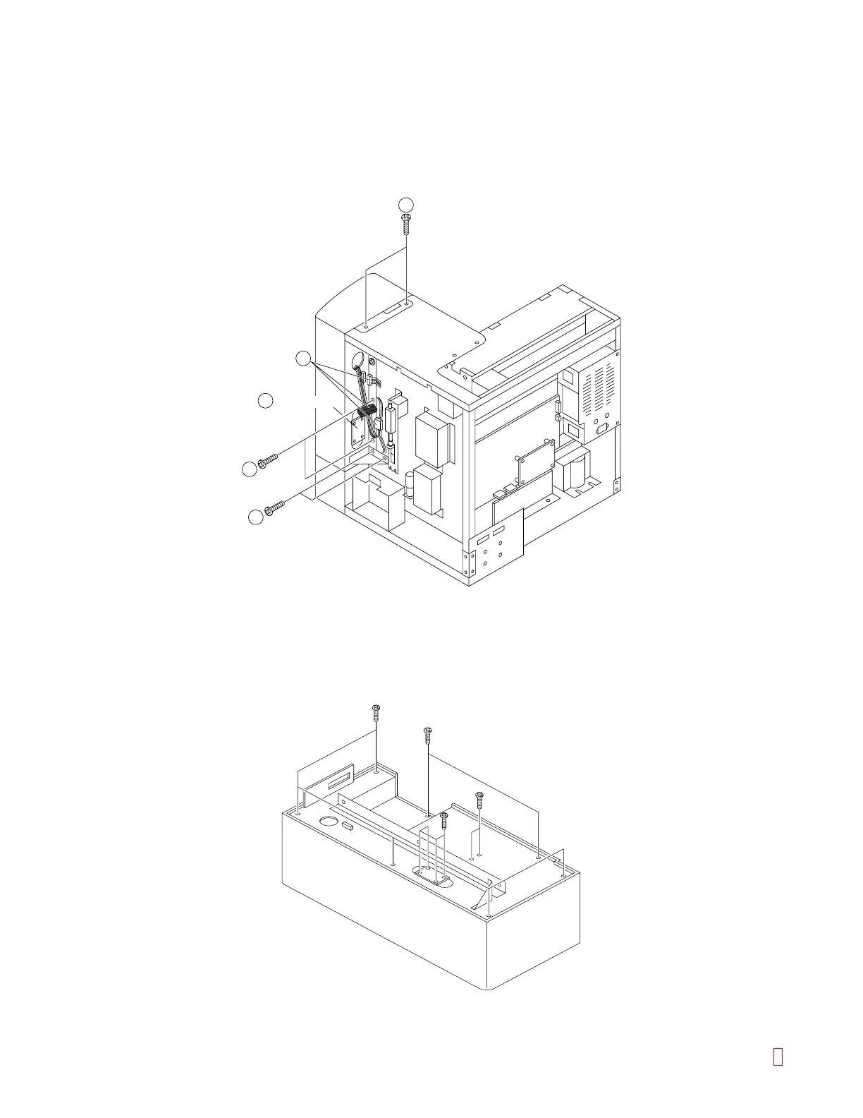
(2) Disconnect (PR RELAY) connector CN1, 7, 8 on PCB No.9265. Disconnect two relay Connectors, and
LCD Connector (item 2).
(3) Remove two screws on the top side (item 3) and four screws on the right side (item 3) to pull Operation
Panel Assembly toward you.
2
2
3
3
3
PCB No.9265
Figure C-13: Removing Operation Panel Assembly
(4) Remove six screws on the back side of Operation Panel Assembly, and you can find Printer, LCD, VR
Assembly and Emergency Stop Switch inside.
(5) PCB No. 9265 is fixed by four screws.
Figure C-14: Operation Panel Assembly
8 CA-500 Series S/M C-8 Revised December 2001