(12) Loosen the tension of the Y-axis Motor by loosening two screws (item 12) and remove the belt by sliding
the motor.
(13) Remove four screws fixing the Z-axis base on the linear slider, and Z-Axis Base Assembly can be
removed (item 13).
12
13
Y Motor
Make loose
Figure C-11: Removing Z-Axis Base Assembly
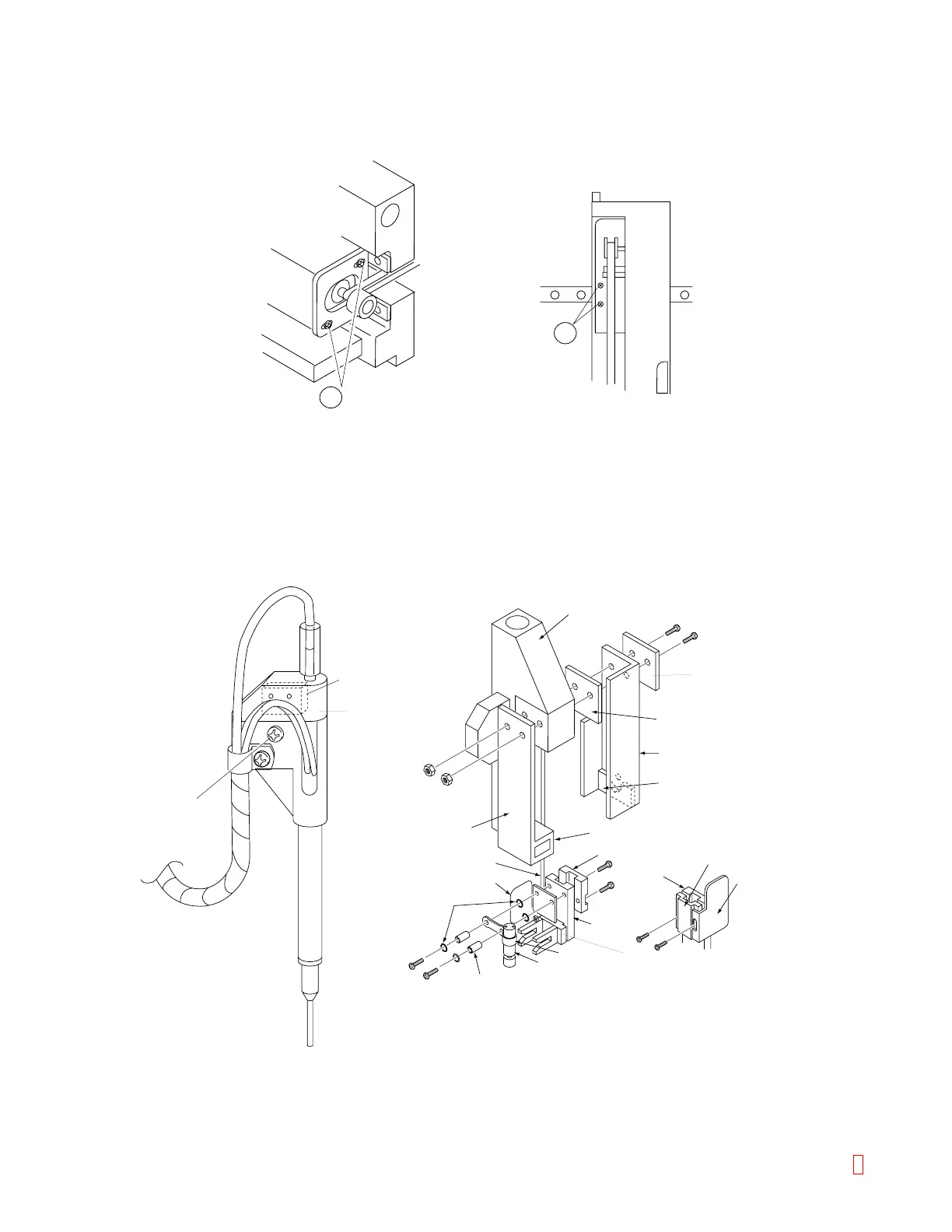
(14) The pipette is fixed by a screw on the upper side.
(15) Crush Sensor is fixed in the pipette cap.
(16) Catcher holder is fixed by two screws together with Leaf Spring, Slider Base, SUS Sub Plate and SUS
Case.
(17) Catcher is fixed together with O-Ring, Spacer, Fixing Metal (SCL6-13) and O-Ring in this order by two
fixing screws.
(18) Z-axis motor is fixed to Z-Axis Base with the SUS plates by two screws
Pipette Fixing Screw
Pipette Crash Sensor
Slider Base
C Sub Plate
Catcher Holder
Catcher Rubber B
Leaf Spring
Catcher Rubber A
Vibration Probe
Tube Sensor Light
Shield Plate
O ring
Spacer
SCL6-B
SCL6-12
(Mixing Motor)
Cord Holder
Tube Sensor Light
Shield Plate
C Arm
C Arm
Cord Holder
SUS Case
Pipette Cap
Catcher
Figure C-12: Catcher Unit Assembly
8 CA-500 Series S/M C-7 Revised December 2001