CA-500 Series S/M C-6 Revised December 2001 8
(6) Open the left side aluminum plate and remove the shaft and Drive Arm Assembly.
(7) Remove the tubing from the clamp by removing two left screws, two screws of your side, three screws on
the top and the four right screws in order to remove Drive Arm Assembly. (The cover can be removed
without removing Drive Arm Assembly from the main unit. Be careful not to catch or crush the tubing.)
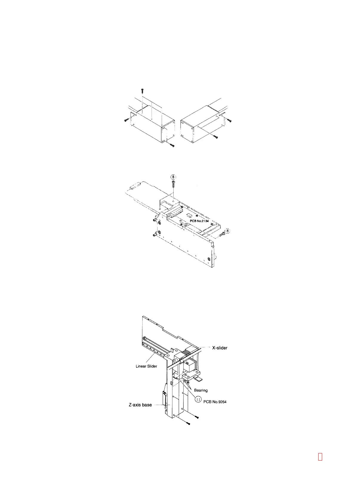
Figure C-8: Removing Drive Probe Unit Cover
(8) After removing the cover, you can access PCB No. 2134.
Figure C-9: Accessing PCB No. 2134
(9) The X-slider can be removed after removing the chassis.
(10) The linear slider and the bearing block on the lower side are included in the X-slider.
(11) After removing six screws fixing the resin cover at the back side of the Z-axis base, you can access PCB
No. 9264 (Z-Axis Home Position Sensor).
Figure C-10: Accessing PCB No. 9264