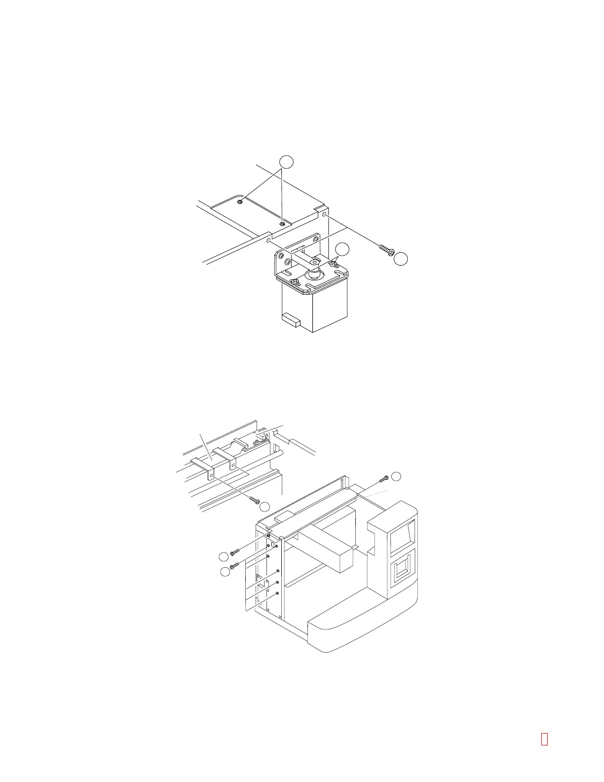
C.4 Drive Arm Assembly
(1) Remove all the panels.
(2) Remove the belt by loosening the tension of X-motor by loosening two screws (item 2). (Be careful, as
the left side idler comes off.)
(3) Remove four screws on the right and left sides and two screws (item 3) on the top side of the top plate
(aluminum plate).
2
3
3
Figure C-6: Removing Drive Probe Assembly
(4) Remove two fixing metals clamping the FPC (item 4), and remove the FPC from PCB No. 9260.
(5) Remove the screw fixing the X-axis shaft and loosen the screw of the aluminum plate on the left side.
FPC
5
3
3
4
PCB No.9260
X-axis Shaft
Figure C-7: Removing FPC
8 CA-500 Series S/M C-5 Revised December 2001