6.4.3 Z Axis Home Position Error
Monitor Timing: At time of home position sensing during operation
Monitor Method: The photo interrupter shades the light of Z axis drive mechanism.
CA-500’s Action: Emergency stop
(1) Probable Cause
1 Drive mechanism operation is obstructed.
2. Loosened pulley of motor
3. Failure of PCB No. 9264
4. Failure of PCB No. 2134
5. Defective light shield
6. Flaws on shaft
7. Failure on bushing
8. Failure of PCB No. 9260
9. Failure of X axis wiring cord
10. Failure of PCB No. 6362
11. Failure of Z axis motor assembly
12. Failure of PCB No. 4086
(2) Confirmation by the Operator
1. Remove the obstruction in Z-axis drive mechanism.
2. Turn off the power supply and turn it on again.
(3) Confirmation by Service Engineer
1. Retighten the screw of the pulley of motor.
2. If home position cannot be detected even when the drive mechanism is operated:
a) Check whether the light shield is defective or not.
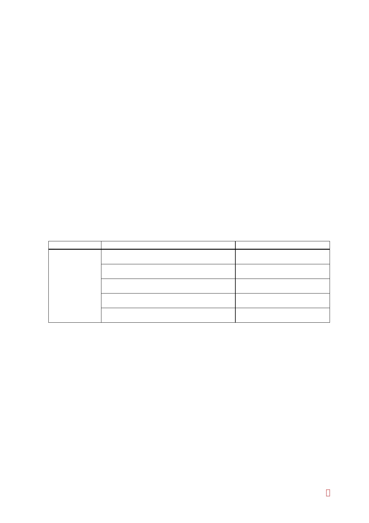
Suspect Part Test Points Expected Value
Position sensor CN1 (PCB No. 9264) pin 9 (GND) and pin 7 5 V Æ 0 V when the sensor is
shielded
CN4 (PCB No. 2134) pin 9 (GND) and pin 7 5 V Æ 0 V when the sensor is
shielded
CN1 (PCB No. 2134) pin 17 and pin 18 (GND) 5 V Æ 0 V when the sensor is
shielded
CN1 (PCB No. 9260) pin 17 and pin 18 (GND) 5 V Æ 0 V when the sensor is
shielded
CN105 (PCB No. 6332) pin 7 and pin 14 (GND) 5 V Æ 0 V when the sensor is
shielded
3. When the motor does not operate,
a) Any of motor, PCB No. 9264, PCB No. 2134, X-axis wiring cord, and PCB No. 4086 is faulty.
b) Turn the pulley by hand. If it does not move, the motor or drive mechanism is faulty.
4. Failure of drive mechanism
a) Check for flaws on the shaft.
b) If the shaft is free from flaws, the problem is in the bushing.
CA-500 Series S/M 6-10 Revised December 2001 8