CA-500 Series S/M 4-3 Revised December 2001
4.1.2 Adjustment of Pressure Indication
(1) Verify that the ambient temperature where the unit is located is within the range of 15°C ~ 35°C. (The
optimum recommended temperature range is 20°C ~ 30°C.)
(2) Connect the Pressure Gauge (with resolution of more than 28 g/cm
2
, which can measure the pressure of
300 g/cm
2
) to the pressure line (black) on the rear panel.
(3) Adjustment procedure:
1) Start Service Mode.
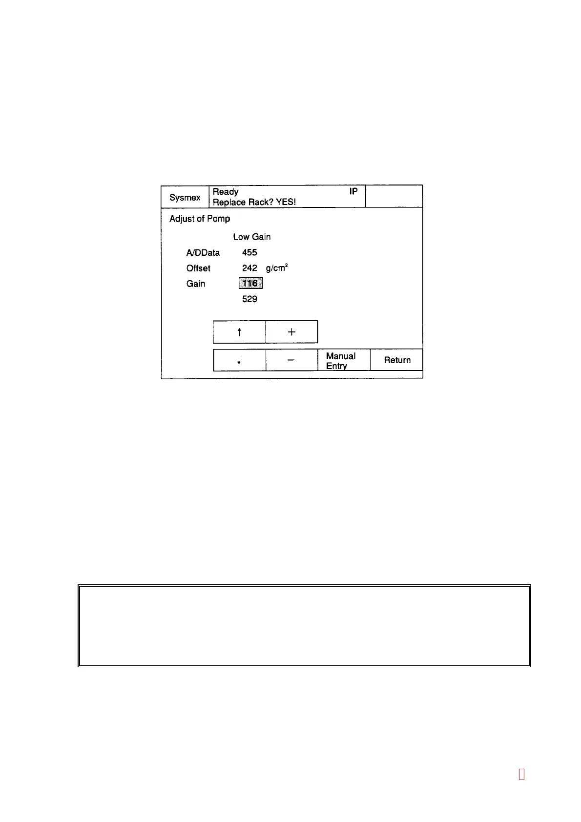
2) Select [Special Operate] Æ [Service] Æ [Adjust] Æ [Adjust. of Pump].
Figure 4-1-4: Adjust Pump Screen
3) Disconnect the tube at the pressure side (the black marking line on the rear panel) to release the
pressure sensor (so that the pressure sensor shows the atmospheric pressure).
4) Offset the cursor by using [n] and [p] keys.
5) Adjust the offset value by using [+] and [-] keys so that the pressure gauge shows 1 g/cm
2
. (When
the offset value is lowered, A/D value also becomes lower.) (Actually, there is a fluctuation of 0 ~ 4
for the value, therefore, adjust it so that it shows the value, which approaches 0 most.)
6) Re-connect the pressure gauge to the pressure line on the rear panel.
7) Move the cursor to the gain by using “n” and “p” keys.
8) Adjust the gain value by using [+] and [-] keys so that the pressure gauge value (adjusted 250 g/cm
2
by the procedure described in 4.1.1 Adjustment of Pressure Detector Circuit) agrees with the
displayed pressure value on CA-500. The difference between the pressure gauge value and
CA-500 displayed value should be adjusted within 3 g/cm
2
.
9) Verify Steps 3) to 8) again, and if the value is within the specified range. Press the [Return] key.
10) Confirmation screen will be displayed by pressing “Return” key.
REFERENCE: Pressure is adjusted at the factory in principle, therefore, it is not necessary to adjust
in the field. Setting values are stored in EEPROM on the PCB No. 6362 or PCB No.
6373.
In case of erasing the EEPROM, these printed values are attached on the memory
card socket.
Select the appropriate key.
FIX: The new setting value is fixed.
Cancel: The new setting value is deleted and Adjust of Pump program will be quitted.
Continue: The adjustment can be continued.
8