CA-500 Series S/M 4-2 Revised December 2001
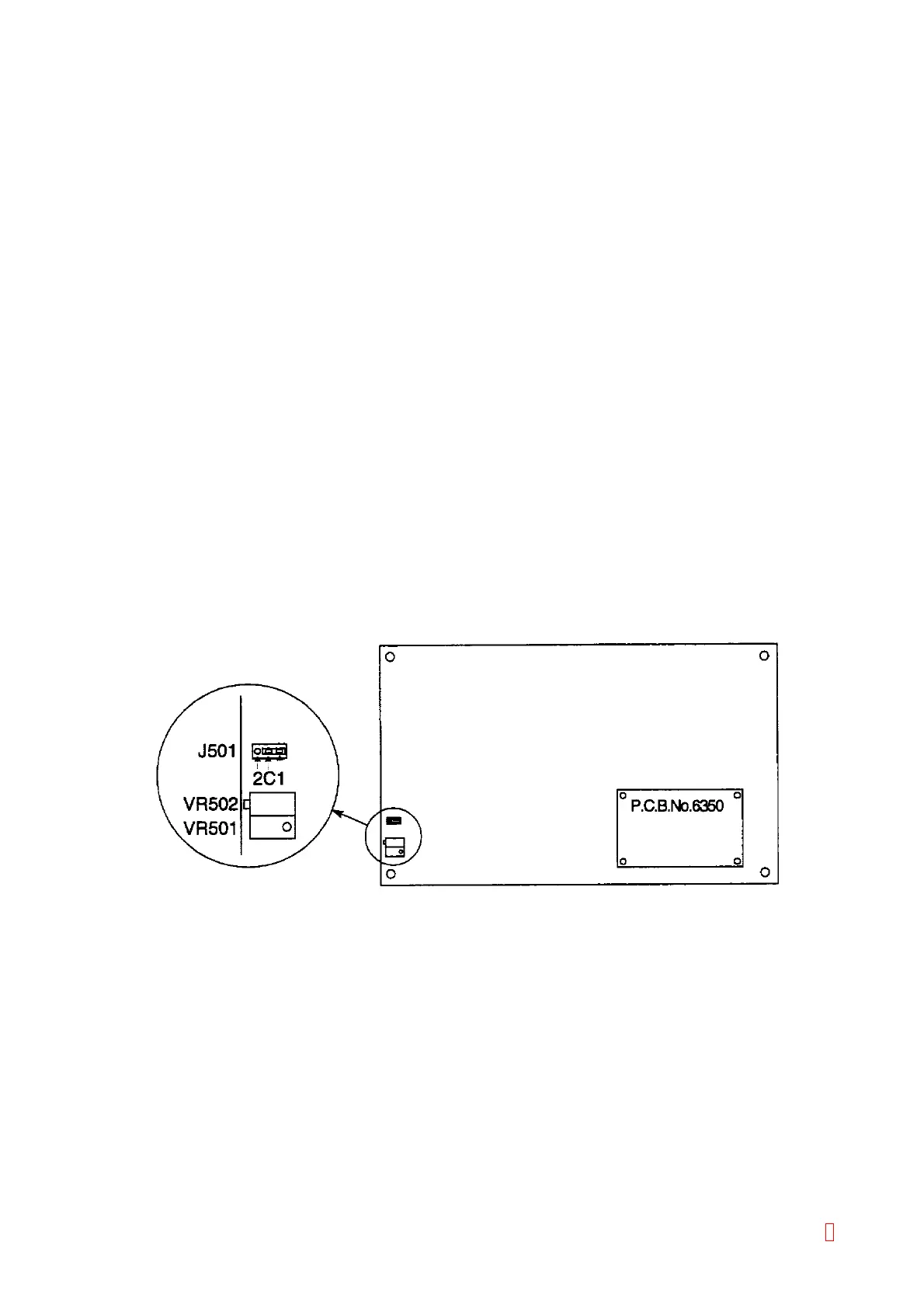
2) Connect Jumper Pin J501 of PCB No. 6362 or PCB No. 6373 to C-2.
3) Loosen and remove the rinse bottle cap carefully because the cap will be lifted up by the pressure inside
the rinse bottle.
4) Disconnect the black marked silicone tube connected to the rear panel at the rinse bottle.
5) Connect the pressure gauge to the silicone tube.
6) Turn the power ON.
7) Adjust the VR502 (OFFSET) so that the pressure becomes 225 ± 3 g/cm
2
. (The pressure will be
increased when VR is turned to CW direction. Disconnect the pressure gauge from the tube once when
adjusting the pressure decreasing.)
8) Remove Jumper Pin J501. (Do not lose the jumper pin because it is placed on the PC board.)
9) Adjust the VR501 (GAIN) so that the pressure becomes 275 ± 3 g/cm
2
. (The pressure will be increased
when VR is turned to CW direction. Disconnect the pressure gauge from the tube once when adjusting
the pressure decreasing.)
10) Verify Steps 1) to 5) again. As the VR502 (OFFSET) and the VR501 (GAIN) are related each other, adjust
them repeatedly until the set values are obtained by repeating Steps 1) to 5).
11) Reconnect Jumper Pin J501 to C-1.
12) Disconnect the tube to decrease pressure, and reconnect it.
13) Verify that pressure is 250 ± 3 g/cm
2
.
* If pressure is not 250 ± 3 g/cm
2
, check and adjust again by repeating Steps 1) to 5).
Figure 4-1-3: PCB No. 6362 Jumper, VR Location
8