6.2 TEMPERATURE ERRORS
6.2.1 Temperature Error (High)/Incubator, Temperature Error (Low)/Incubator
Monitor Timing: When READY: 1-minute interval
When analyzing: At time of reagent dispensing
Monitor Method: A/D converter reads the thermistor data embedded in the sample probe as follows:
Room temperature less than 30qC: Temperature error when exceeds the range 36.0 -
38.0qC.
Room temperature above 30qC: Temperature error when exceeds the range 36.0 -
40.0qC.
CA-500’s Action: When the error occurs before the analysis, the analysis does not start. During analysis,
operation is continued with "Temperature Error" added to stored data.
(1) Probable Cause
1. Room temperature became outside the range between 15 - 35qC.
2. Thermistor failure
3. Heater failure
4. Failure of PCB No. 2134
5. Failure of X-axis wiring cord
6. Failure of PCB No. 9260
7. Failure of PCB No. 6362
8. Failure of PCB No. 4086
(2) Confirmation by the Operator
1. Confirm room temperature by checking temperature displayed on the main unit.
(3) Confirmation by the Service Engineer
1. Check the main unit fan is operating or not. if not, inside temperature rises, causing it impossible to
keep the detector at 37°C.
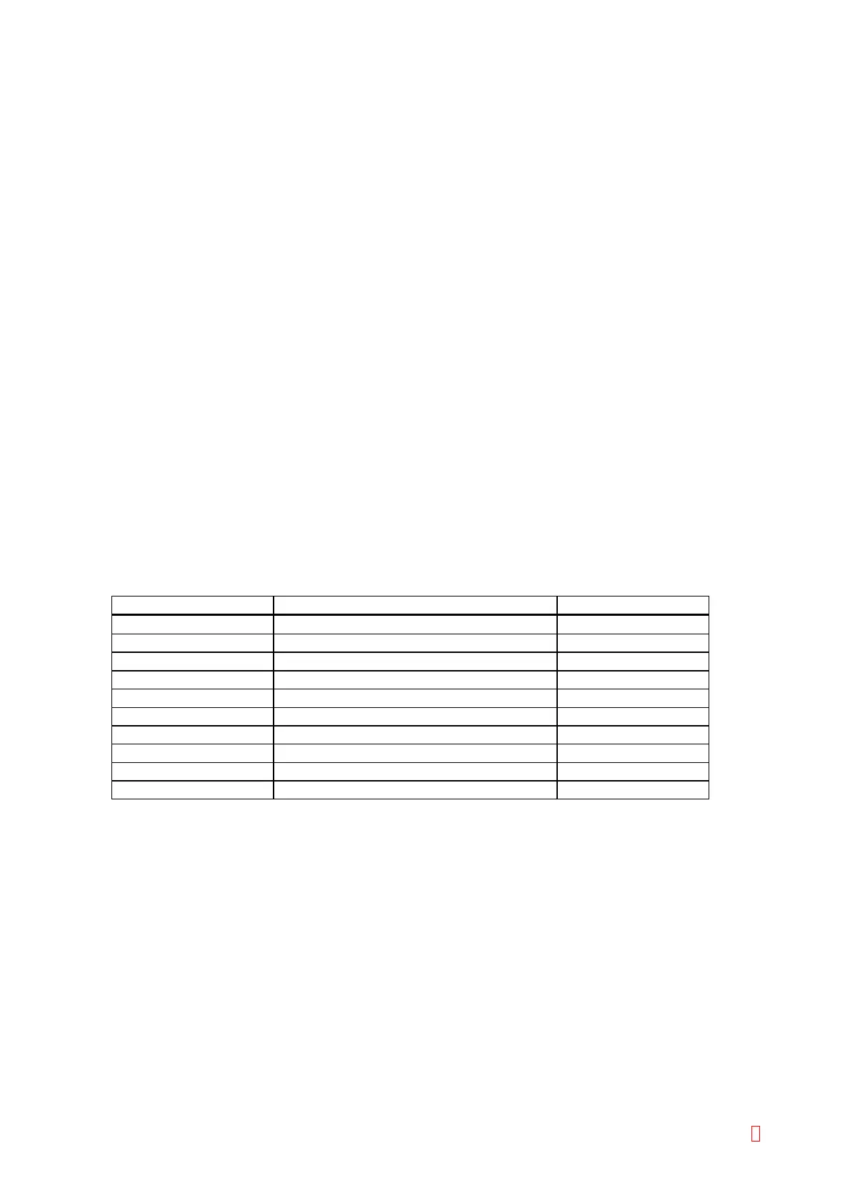
Suspect Part Test Points Expected Value
Thermistor CN3 pin 3 and pin 6 on PCB No. 2134
3 K: to 4 K:
Heater CN3 pin 1 and pin 2 on PCB No. 2134
10 K: to 20 K:
PCB No. 2134 CN3 pin 12 and pin 15 on PCB No. 2134
3 K: to 4 K:
PCB No. 2134 CN1 pin 8 and pin 9 on PCB No. 9260
10 K: to 20 K:
X-axis Wiring Cord CN1 pin 12 and pin 15 on PCB No. 9260
3 K: to 4 K:
X-axis Wiring Cord CN1 pin 8 and pin 9 on PCB No. 9260
10 K: to 20 K:
PCB No. 9260 CN3 pin 8 and pin 9 on PCB No. 9260
3 K: to 4 K:
PCB No. 9260 CN4 pin 15 and pin 16 on PCB No. 9260
10 K: to 20 K:
PCB No. 6362 CN105 pin 8 and pin 9 on PCB No. 6362
3 K: to 4 K:
PCB No. 4086 CN14 pin 15 and pin 16 on PCB No. 4086
10 K: to 20 K:
CA-500 Series S/M 6-3 Revised December 2001 8