CA-500 Series S/M 4-34 Revised December 2001 8
4.5.2 PCB No. 4086: PS (Power Source, Motor Driver)
4.5.2.1 CA-500 Power Supply System Check
Check the voltages for each switching regulator and PS Board (PCB No. 4086), following the procedure
below.
(1) Make sure that the Main Unit Power of CA-500 is turned OFF.
(2) Disconnect the following connectors to be free from any load:
CN101, CN104 on MAIN BOARD (PCB No. 6362)
CN2 on PRCN1 (PCB No. 6350)
(3) Turn the CA-500 Main Unit power OFF.
(4) Make sure that the voltage on each switching regulator and PS Board (PCB No. 4086) shows the
output voltage in Table below. (There is no adjusting point.)
(5) Turn the power switch of the CA-500 Main Unit OFF and connect CN101, CN104 on Main Board
(PCB No. 6362) with CN2 on PCN1 (PCB No. 6350).
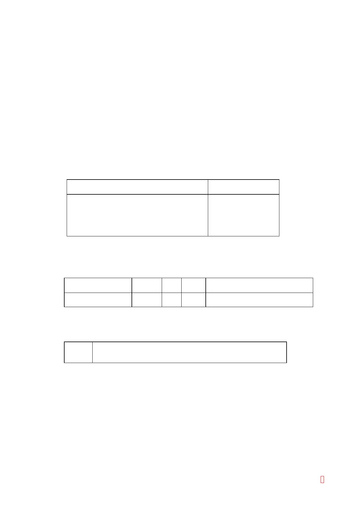
PS BOARD (PCB No. 4086) Connector
(The other side is connected to TP1 (GND))
Output Voltage
CN14 pin 9 +24 V ± 1 V
CN8 pin 5 +12 V ± 0.5 V
CN12 pin 3 +5 V ± 0.2 V
CN9 pin 3 +5 V ± 0.2 V
CN12 pin 1 +15 V ± 0.6 V
CN12 pin 2 –15 V ± 0.6 V
4.5.2.2 LED and Test Point
(1) LED
Sensor Letters
on PCB
LED Color Status
Liquid Surface Sensor LIQUID D7 Red Lit when the liquid surface is detected
Probe Crash CRASH D8 Green Lit when the probe crashes
These LEDs turn OFF by the RESET signal (P-RES).
(2) Test Point
TP1 GND
TP2 Analog Signal of Liquid Surface Detection for checking
TP3 Comparator Output Signal of Liquid Surface Detection for checking