6.4.6 Tube Release Error (Position)
Monitor Timing: Just after the reaction tube releasing operation
Monitor Method: Monitoring tube detection sensor condition
CA-500’s Action: Interruption
(1) Probable Cause
1. A tube cannot be released.
2. Tube detection sensor is obstructed.
3. The waste box of tube is full.
4. The catcher is too dirty to function.
5. Mis-position of catcher
6. Defective catcher
7. Failure of tube detection sensor
8. Failure of PCB No. 9264
9. Failure of PCB No. 2134
10. Failure of PCB No. 9260
11. Failure of X axis wiring cord
12. Failure of PCB No. 6362
(2) Confirmation by the Operator
1. Empty the waste box if it is full of the reaction tube.
2. Remove anything that is obstructing the release operation.
3. Wash away any contamination on catcher by using alcohol.
(3) Confirmation by Service Engineer
1. When Tube Release Error has occurred:
a) Correct any mis-positioning of the catcher if that has happened.
b) Replace the catcher.
2. When an error occurs although a tube is released:
a) The sensor functions up to 30 mm apart from tubes. Keep away any objects that reflect light to
cause release error.
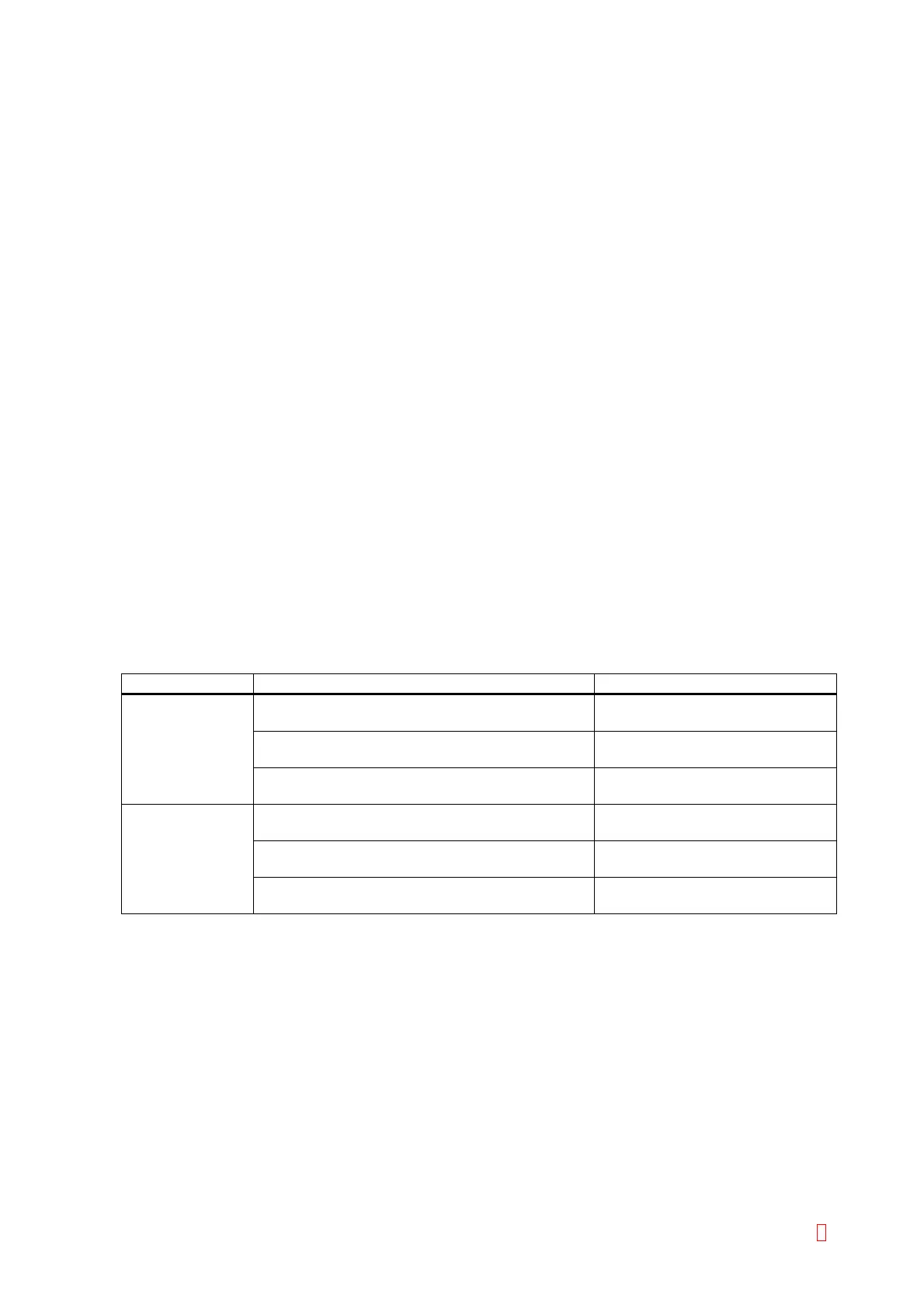
Suspect Part Test Points Expected Value
Tube Detection
Sensor
CN2 (PCB No. 9264) pin 3 (GND) and pin 2 5 V Æ 0 V when a tube is
detected
CN1 (PCB No. 9264) pin 13 (GND) and pin 8 5 V Æ 0 V when a tube is
detected
CN4 (PCB No. 2134) pin 13 (GND) and pin 8 5 V Æ 0 V when a tube is
detected
CN1 (PCB No. 2134) pin 16 (GND) and pin 4 5 V Æ 0 V when a tube is
detected
CN1 (PCB No. 9260) pin 16 (GND) and pin 4 5 V Æ 0 V when a tube is
detected
CN105 (PCB No. 6362) pin 13 (GND) and pin 1 5 V Æ 0 V when a tube is
detected
CA-500 Series S/M 6-13 Revised December 2001 8