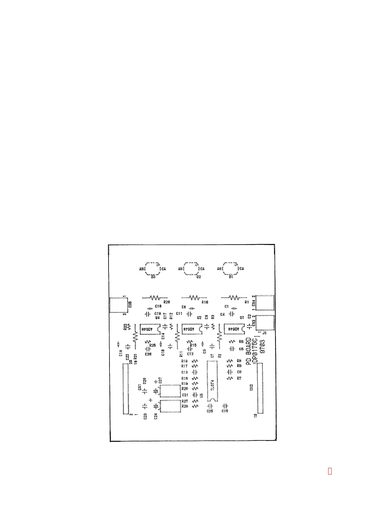
3.3.3 Circuit Explanation
(1) Pre Amplifier Circuit
1) Current/Voltage Converter (U1, 2, 4)
The photo-diode receives scattered light and generates small electric current. This circuit
converts this current into a voltage.
2) Low-pass Filter (R6 + C5, R15 + C12, R25 + C20)
Low-pass filter reduce the noise.
3) Amplifier (U3)
The channels CH1~CH4 are the direct current amplifier with a gain of 11 times.
The channel CH5 and CH6 are the direct current amplifier with a gain of 1 time.
4) Constant Current Circuit for CH6 (U3C, U5, Q1, PC1)
The shunt regulator (U5) releases reference voltage and releases the constant current circuit
by comparing the voltage released from U3 to R32. PC1 controls isolated LED electricity
ON/OFF signal from MAIN (PCB No. 6362) or MAIN-2 (PCB No. 6373) and Q1 turns on
constant current by ON/OFF. R23~R26 bleeds only to turn LED for CH6.
3.3.4 Setting and Adjustment
Setting and adjustments are not necessary.
3.3.5 LED and Test Point
There is no LED and Test Points.
3.3.6 Assembly Drawing
Figure 3-5: PCB No. 2132 Assembly Drawing
CA-500 Series S/M 3-7 Revised December 2001 8