CA-500 Series S/M C-2 Revised December 2001 8
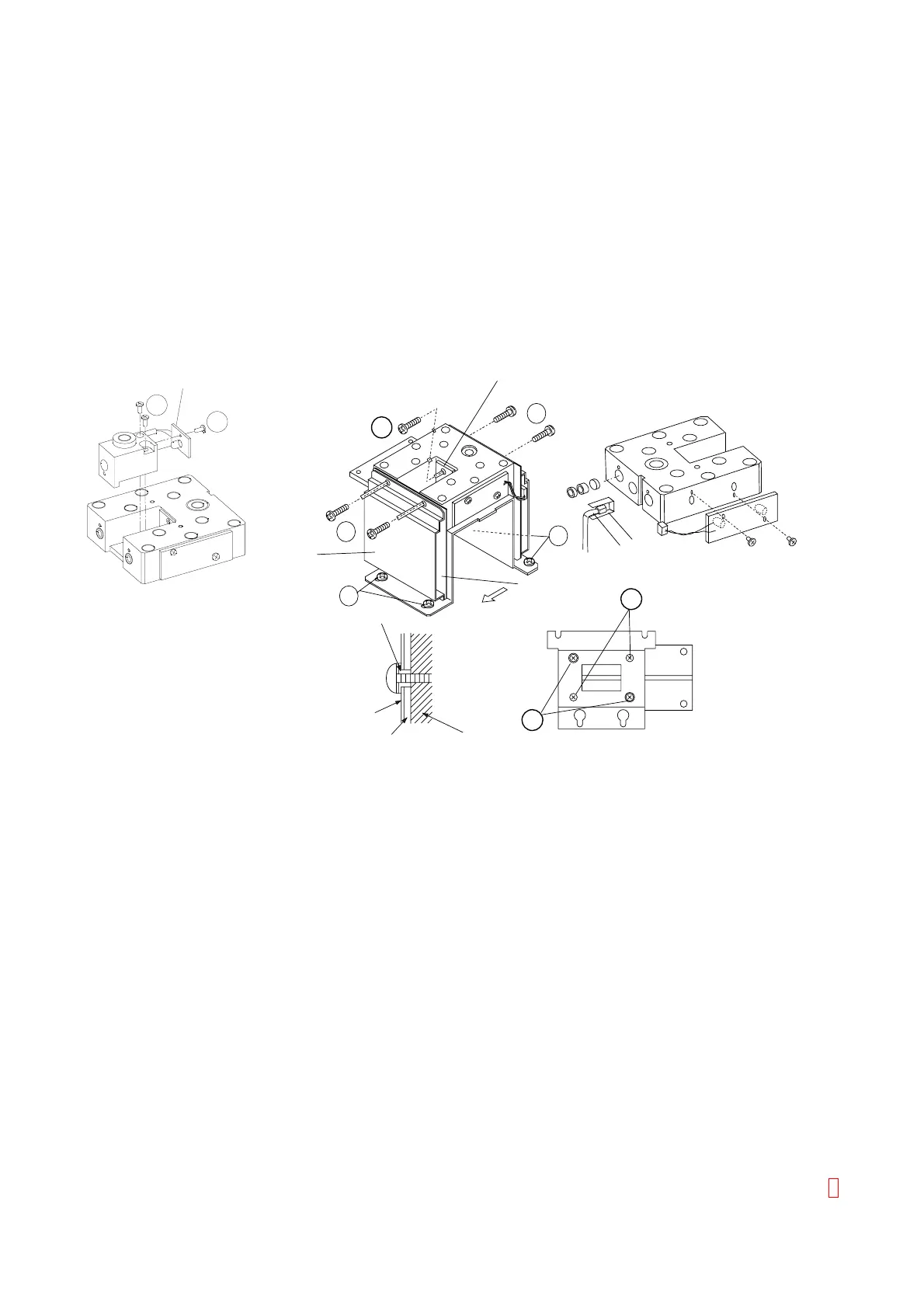
(5) For Detector Unit Assembly, loosen Four fixing screws (item 5 in the Figure C-2), and remove it by sliding
to the left side.
(6) Disconnect relay Connector and PCB Connectors.
(7) Channel 6 is fixed by two screws.
(8) PCB No. 9259 (Immuno, LED) is fixed by one screw.
(9) PCB No. 9259 (AT3, LED) is fixed by one screw.
(10) PCB No. 2132 is tightened by four screws together with Shield Case. (Including Isolation Bush.)
(11) PC Board of Photo Diode for AT-3 is fixed to Heater Block by one screw.
(12) Thermal Sensor is inserted in the Block with Sarcon®.
(13) Turn over the Block and remove the aluminum plate by removing two screws. (item 11)
(14) Remove two fixing screws (item 12) on the aluminum plate to remove the heater.
7
PCB No.9259
8
5
6
5
11
6
7
12
Slide
Isolation Bush
Shield Case
Optical Block
Thermal Sensor
PCB No.2132
PCB No.9259
Sarcon®
Shield Case
PCB No.2132
Figure C-2: Disassembling Detector Unit
9
13
14