+24V
X
(STK6713B)
+24V
Y
(STK6712B)
+24V
Z
(STK6712B)
+24V
(STK6712B)
+12V
(TA8415)
(TD62308)
EN
CW/CCW
CLK
ON/OFF
AC100V-1
AC100V-2
ON/OFF
AC100V-1
AC100V-2
from PCB No. 6362 (MAIN)
from PCB No. 6362 (MAIN)
from PCB No. 6373 (MAIN-2)
from PCB No. 6373 (MAIN-2)
from PCB No. 6373 (MAIN-2)
from PCB No. 6373 (MAIN-2)
from PCB No. 6373 (MAIN-2)
from PCB No. 6373 (MAIN-2)
from PCB No. 6373 (MAIN-2)
from PCB No. 6362 (MAIN)
from PCB No. 6362 (MAIN)
from PCB No. 6362 (MAIN)
Syringe
ID Unit Motor
Buffer
Buffer
Buffer
Buffer
Constant
Current
Drive IC
Constant
Constant
Constant
Current
Current
Current
Drive IC
Drive IC
Drive IC
Stepper Motor
pulse
ganerator
Constant
Current
Drive IC
from PCB No. 6362 (MAIN)
from PCB No. 6362 (MAIN)
Pressure Pump
Vacuum Pump
AC Power
Photo-
AC Power
Coupler
Photo-
Coupler
to Stepper motor for X-Axis
to Stepper motor for Y-Axis
to Stepper motor for Z-Axis
to Stepper motor for Syringe
to Stepper motor for ID Unit
to Pressure Pump
to Vacuum Pump
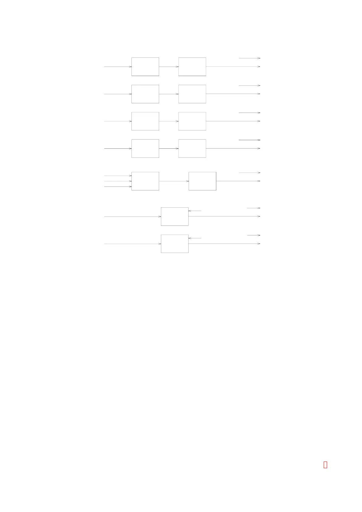
Figure 3-8-b: PCB No. 4086 Block Diagram (Continued)
3.6.3 Circuit Explanation
(1) Stepper Motor Control Circuit for X-Y-Z Drive mechanism and Syringe
This stepper motor operates by the two-phase constant current drive.
(2) Motor Drive Circuit for ID Unit
TD62308 drives the stepper motor by the four-phase pulse generated at TA8415 from the CLK signal
generated on PCB No. 6362 (MAIN) or PCB No. 6373 (Main-2). This stepper motor is operated by
the two-phase voltage drive.
(3) Vacuum, Pressure Pump Driver Circuit
This circuit turns the vacuum and pressure pumps ON/OFF at TLP3503 by the control signal from
PCB No. 6362 (MAIN) or PCB No. 6373 (Main-2). The vacuum and pressure pumps are operated at
AC 100 V.
3.6.4 Setting and Adjustment
Setting and adjustments are not necessary. Refer to Section 4 to verify each voltage.
3.6.5 LED and Test Point
(1) LED
No LED is used.
(2) Test Point
TP1: GND
CA-500 Series S/M 3-13 Revised December 2001 8