41
2. INSTALLATION
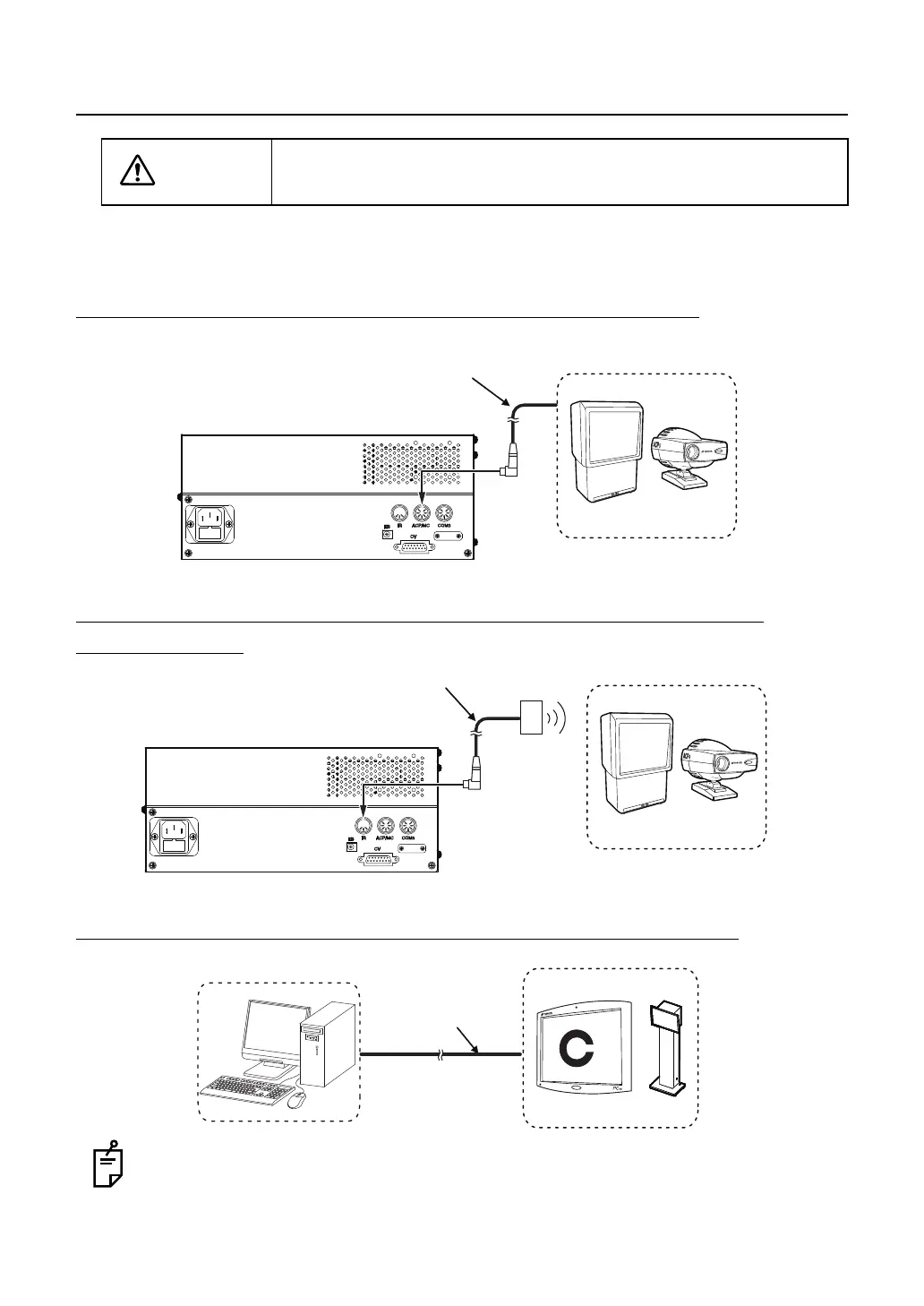
2.3 CONNECTING THE VISUAL ACUITY CHART
There are three types of the methods to connect the visual acuity chart. Use the connection
method applicable to the purchased chart.
CONNECTING A DEVICE TO RS-232C (ACP-8, MC-3.)
CONNECTING A DEVICE TO INFRARED COMMUNICATION
(ACP-8, MC-3.)
CONNECTING A DVI DEVICE (PC-50S, PC-50SB, MC-4S)
Connect the image cable to the DVI terminal of the personal computer.
Refer to the instruction manual of your personal computer for details.
CAUTION
Install the visual acuity chart out of the CV-5000 patient's environ-
ment.
Communication cable (DIN/DIN)
or
Communication cable (DIN/D-sub)
Power supply unit
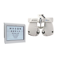
Visual acuity chart (ACP-8, MC-3)
Infrared communication unit
Visual acuity chart (ACP-8, MC-3)
Power supply unit
Image cable
Personal computer
Visual acuity chart
 Loading...