Getting Acquainted
1-866-4TOPCON www.topconpositioning.com
1-15
Front Panel
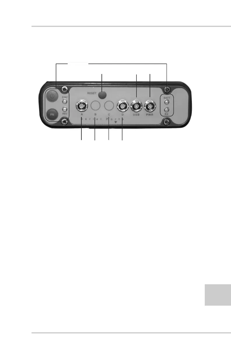
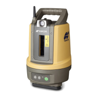
Figure 1-3 shows the front panel components.
Figure 1-3. HiPer+ Front Panel
• MINTER – The Minimum INTERface for the
HiPer+ receiver. The MINTER consists of two keys
and four, three-color LEDs. See “Using the
MINTER” on page 4-1 for descriptions and usages
of the MINTER components.
• Reset – Pressing this key performs a hard reset for
both the receiver board and the power board. Once
this key is pressed, the controllers governing the
receiver board, power board, and Bluetooth module
reboot and the device restarts.
This key can be used to leave Zero Power Mode or if
the receiver does not respond to commands. See
“Using the MINTER” on page 4-1 for details.
• Four serial ports:
–Port A used for communication between HiPer+
and a controller or any other external device.
–Port B used internally to connect the receiver board
with the Bluetooth module.
ABCD
USB PowerReset
MINTER