PROCEDURE
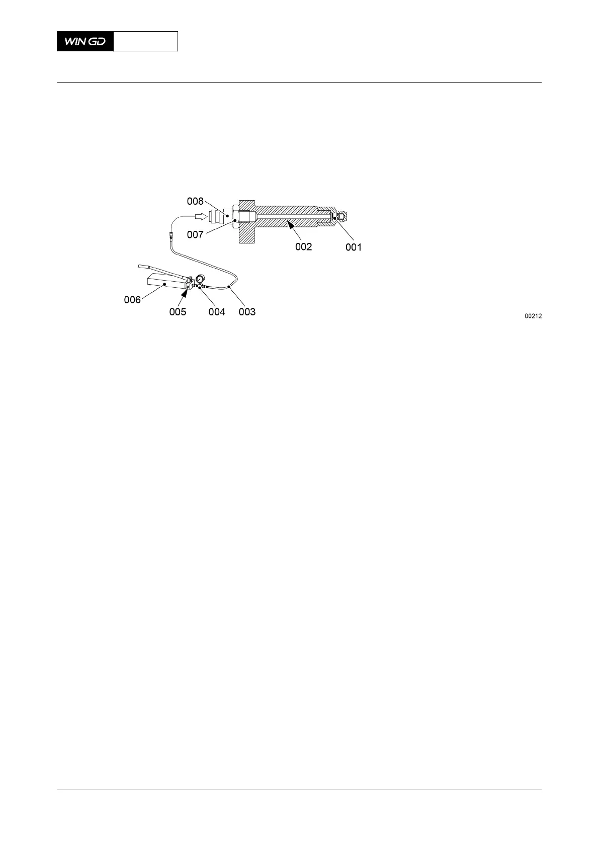
1 If necessary, remove the union (007, Figure 7-14) on the lubricating quill (002).
Fig 7-14 Lubricating quill
2 Attach the distributing piece (004) to the HP oil pump (006).
3 Attach the connection nipple (008) to the lubricating quill (002).
4 Connect the HP hose (003) to the nipple (008) and to the distributing piece (004).
5 Hold the lubricating quill (002) so that the non-return valve (001) points up and points
away from your body.
6 Operate the HP oil pump (006) until oil that has no air flows out.
7 Open the relief valve (005) to decrease the pressure to 2.0 bar.
8 Close the relief valve (005).
9 Hold the lubricating quill (002) in a horizontal position so that it points away from your
body.
10 Operate the HP oil pump (006) to increase the pressure in steps of 1.0 bar until the non-
return valve (001) opens.
11 Record the pressure shown on the pressure gauge (004).
NOTE: The minimum permitted pressure to open the non-return valve is 4.25 bar. If
necessary, replace the defective lubricating quill (002).
12 Open the relief valve (005) to release the pressure to zero.
13 Remove the nipple (008) and the HP hose (003) from the lubricating quill (002).
CLOSE UP
• None
X62DF
AA00-2138-00AAA-340A-A
Maintenance Manual Lubricating quill - do a functional test
Winterthur Gas & Diesel Ltd.
- 197 - Issue 002 2020-10