PROCEDURE
1 Put the template (001, Figure 8-73) in position on the top piston ring (002).
2 Turn the template (001) around the axis of the piston head.
3 Use the feeler gauge to measure the depth of the burn scar(s).
NOTE: You can also use a depth gauge to measure the depth of the burn scar(s).
4 Remove the template (001).
5 If the burn scars are less than 10 mm, do as follows:
5.1 Use an applicable tool to grind the burn scars.
5.2 Use emery paper to make sharp edges smooth.
6 If the burn scars are 10 mm or more, do as follows:
6.1 Disassemble the piston head, refer to section 8.7.4 Piston - disassemble.
6.2 Use surface welding to get the piston head to its original thickness.
6.3 Assemble the piston, refer to section 8.7.6 Piston - assemble.
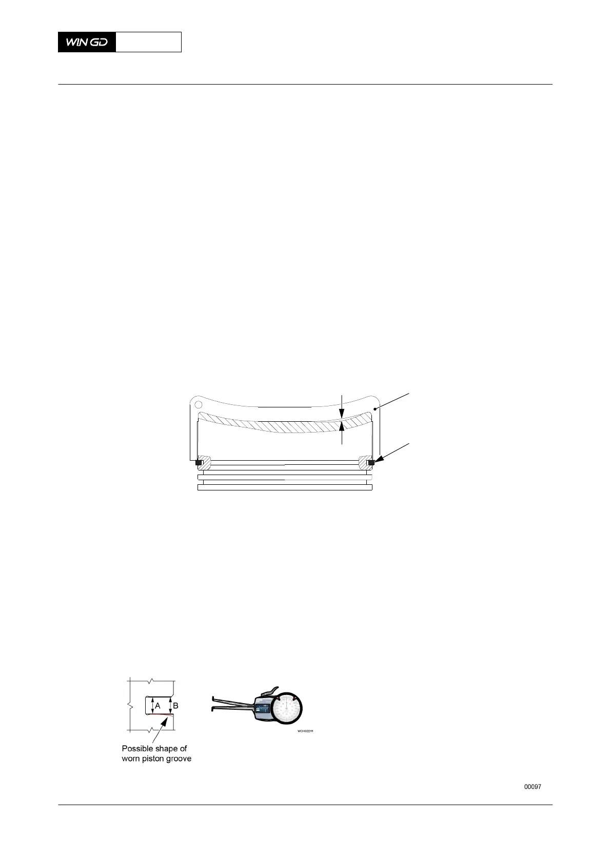
Fig 8-73 Top surface - dimensions check
7 Find the cause of the burn scars and repair the fault.
8 Measure the thickness of the first piston ring at a minimum of four locations around the
circumference of the first piston ring.
9 Measure the height at point A and point B at a minimum of four locations around the
circumference of the related piston groove.
NOTE: You can use the calliper gauge or the inside micrometer set. If you have none
of these instruments, you can use a piece of a piston ring and a feeler gauge.
Fig 8-74 Piston groove clearance - calliper gauge
X62DF
AA00-3403-00AAA-360B-A
Maintenance Manual Piston (removed) - do checks of the surface and clearances
Winterthur Gas & Diesel Ltd.
- 491 - Issue 002 2020-10