13 Torque symmetrically the Allen screws (006, 002).
14 Lock the Allen screws (006) with the locking plates (010).
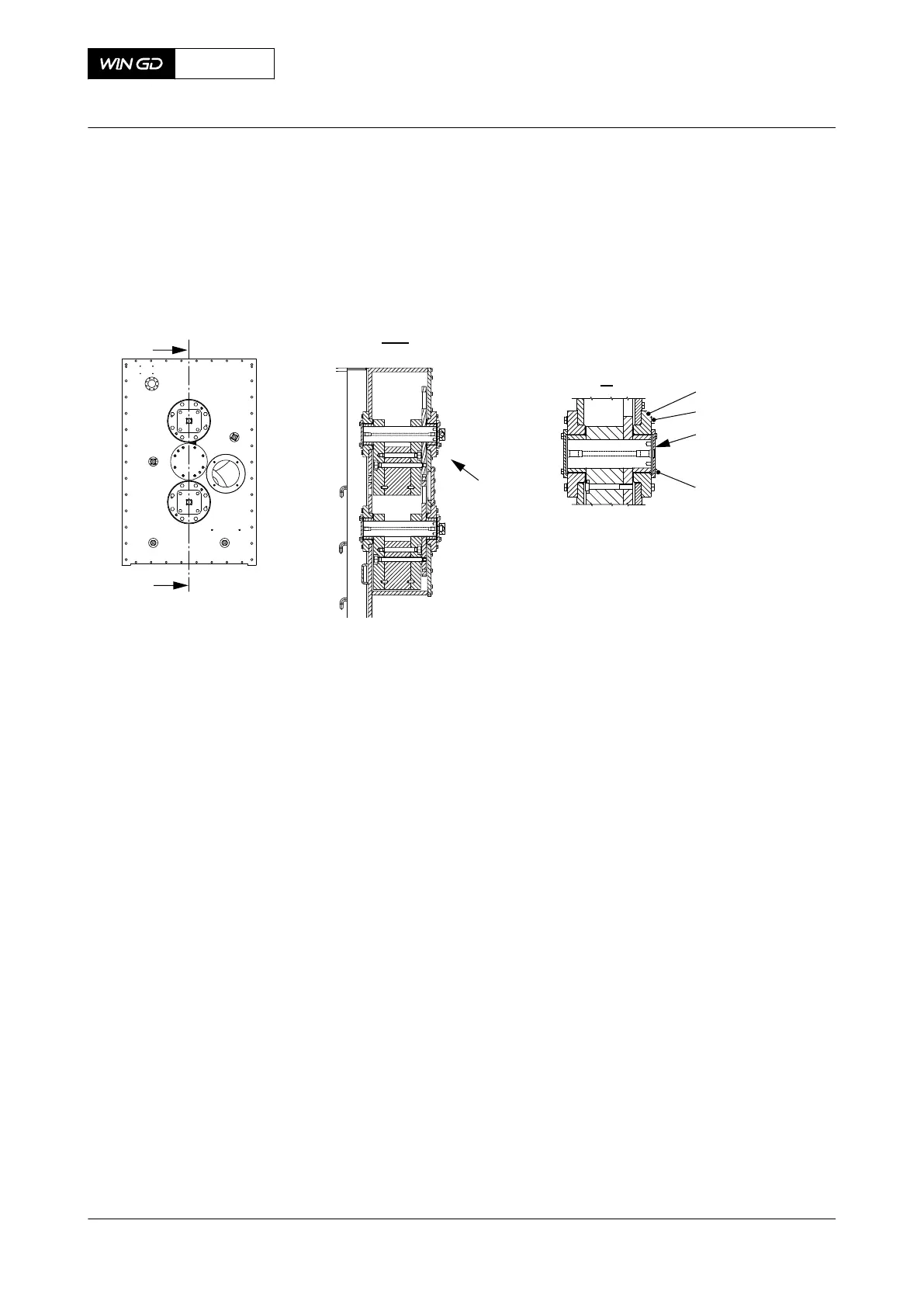
15 Install the applicable oil pipe (002, Figure 12-13).
Fig 12-13 Integrated electric balancer
00540
002
001
001
DRIVING END / FREE END
FUEL SIDE
16 Open the oil inlet.
17 Start the lubricating oil supply.
CLOSE UP
• None
X62DF
AA00-7758-00AAA-360A-A
Maintenance Manual Integrated electric balancer - do a check of the bearing clearance
Winterthur Gas & Diesel Ltd.
- 696 - Issue 002 2020-10