PROCEDURE
1 Attach a new gasket (010, Figure 7-20) to the bush (007).
2 Install the GAV into the bush (007).
3 Attach the pressure reducing valve (013) to the bush (007).
4 Connect a pressurized air supply to the pressure reducing valve (013).
5 Set the pressure reducing valve (013) to 10 bar.
6 Apply WD40 (or an approved alternative) as a spray to the items that follow:
•
Area of the sealing faces (014, 016) of the valve seat
•
Gasket (010).
7 Start the pressurized air supply.
8 Look for the conditions that follow:
•
A maximum of five bubbles each second comes from the valve seat.
•
No bubbles come from the gasket (010).
9 If the test results are different than those given, do the procedure given in Step 13.
10 Stop the pressurized air supply.
11 Remove the pressurized air supply from the pressure reducing valve (013).
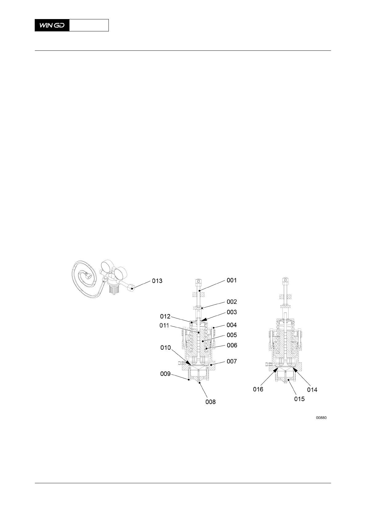
Fig 7-20 Gas admission valve - pressure check
12 Dismantle the spring as follows:
12.1 Install the dismantling and assembling tool to the bush (007).
12.2 Install the bracket (015) to the bush (007) with the screws (009).
12.3 Turn fully in the special screw (008).
12.4 Turn the rod (001) to compress the spring (006).
12.5 Remove the valve cotter (003).
X62DF
AA00-2140-00AAA-362A-A
Maintenance Manual Gas admission valve - do a check for gas leakage
Winterthur Gas & Diesel Ltd.
- 211 - Issue 002 2020-10