PROCEDURE
1 Remove all the protection from the sealing faces, the injection valve and the flow limiting
valve.
2 Attach new O-rings to the flanges (002, 006).
3 Apply Never-Seez NSBT to threads of the Allen screws (004 and 008, Figure 13-10).
4 Carefully put the HP injection pipe (001) in position in the injection valve (005) and the
flow limiting valve (003).
5 Torque symmetrically the four Allen screws (004) to the correct value, refer to section
16.1 Tightening instructions.
6 Torque symmetrically the four Allen screws (007) to the correct value, refer to section
16.1 Tightening instructions.
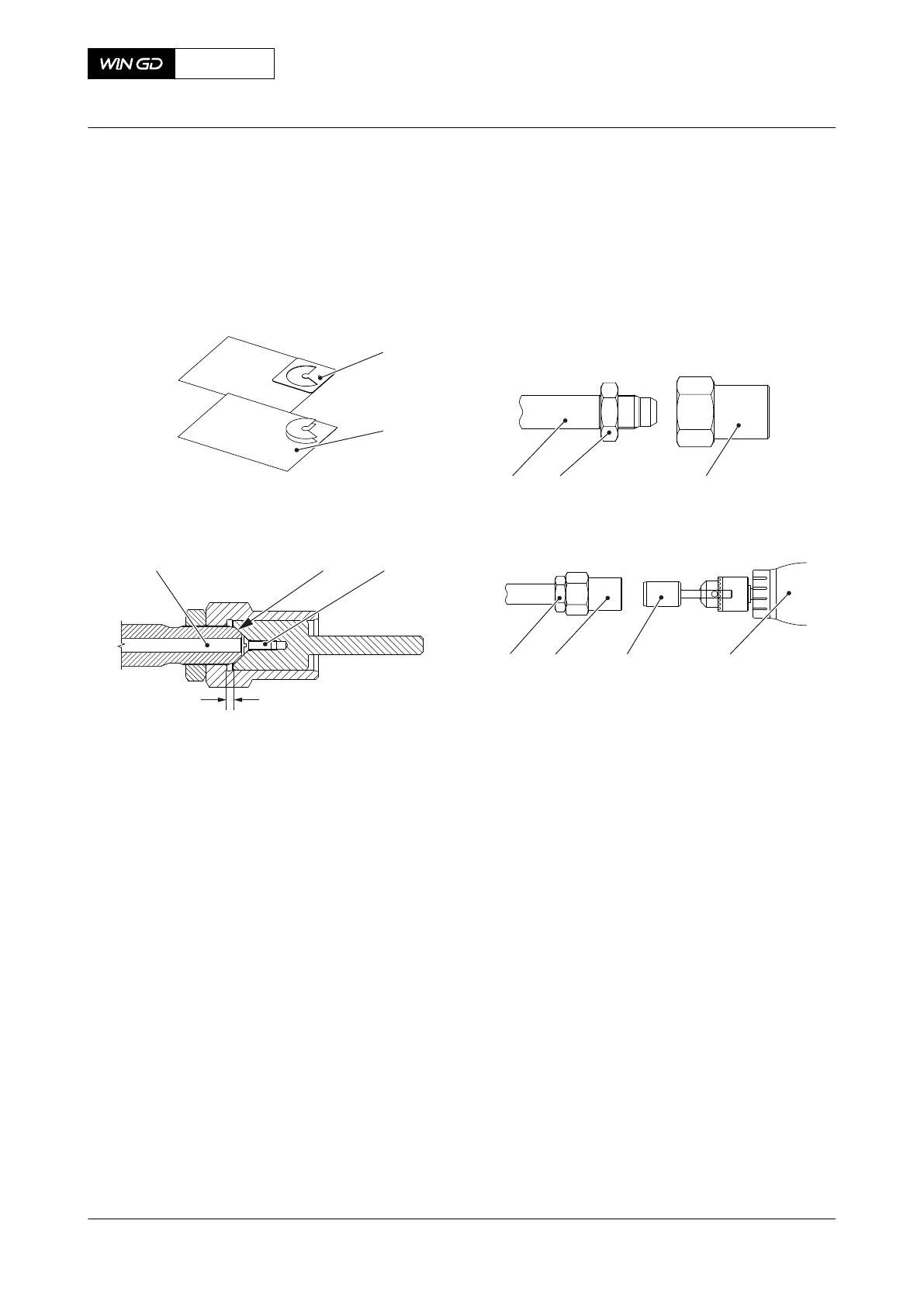
7 Make sure that the distance X between the flange (002, 006) and the end of the pipe
refers to Table 13-3 - Distances X and Y for HP fuel pipe.
Tab 13-3 Distances X and Y for HP fuel pipe
Engine type Distance X [mm]
X52
X52DF
xxx
X62 / -B
X62DF
xxx
X72 / -B
X72DF
5.8
X92 / -B
X92DF
6.0
X62DF
AA00-8733-00AAA-720A-A
Maintenance Manual HP fuel pipe (fuel rail to injection valve) - install
Winterthur Gas & Diesel Ltd.
- 749 - Issue 002 2020-10