15 Apply a thin layer of heat-resistant lubricant to the sealing faces and the screws (001,
005).
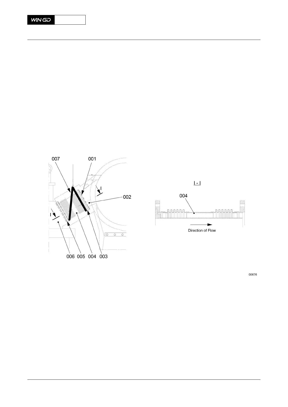
16 Put the two slings (007) in position on the expansion piece (004).
17 Attach the slings (007) to the engine room crane.
18 Operate the engine room crane to lift the expansion piece (004).
19 Put the expansion piece (004) in position between the valve cage (006) and the exhaust
pipe (002). Make sure that the expansion piece is in the correct position.
20 Attach the expansion piece (004) to the valve cage (006) and the exhaust pipe (002)
with the screws (001, 005) and the nuts (003).
21 Remove the two slings (007).
Fig 7-70 Expansion piece - installation
22 Complete the installation of the exhaust valve.
22.1 Tighten the round nuts (004, Figure 7-71), refer to section 4.2 Tighten a round
nut with a pre-tensioner.
22.2 Connect the plug (005) to the valve stroke sensor.
22.3 Install the hydraulic pipe (001), refer to section 13.1.3 HP servo oil pipe - install.
22.4 Install all other pipes to the exhaust valve.
X62DF
AA00-2751-00AAA-720A-A
Maintenance Manual Exhaust valve - install
Winterthur Gas & Diesel Ltd.
- 324 - Issue 002 2020-10