PROCEDURE
1 To install an LDU-20 in the local control panel do the steps that follow:
NOTE: The LDU-20 in the local control panel is the master. You must replace this
LDU-20 only with the item from the engine control room (ECR).
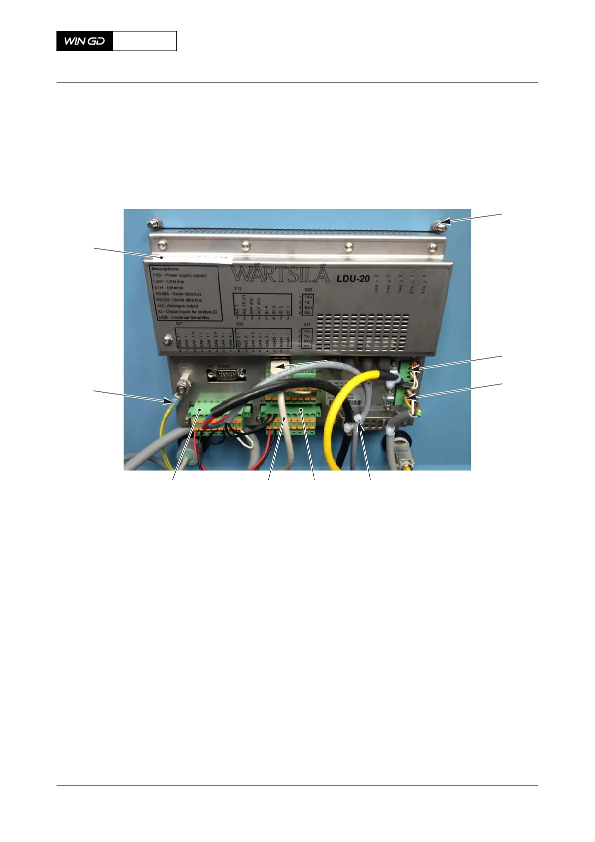
Fig 14-10 LDU-20 rear view
008
00137
003
009
007 006 005 004
002
001
1.1 Attach the LDU-20 (009, Figure 14-10) to the control box E25 with the four
spring washers and nuts (001), refer to the Operation Manual.
1.2 Connect the earth cable (008) to the connection on the LDU-20.
1.3 If installed, connect the USB cable (006).
1.4 Connect the cables to the service connection (002).
1.5 Connect the cables to the Ethernet connection (003).
1.6 Connect the plugs X21 (007) and X22 (005) to the connections on the LDU-20.
1.7 Attach four new cable ties (004) to the positions shown.
1.8 Attach a new label to identify the LDU-20.
1.9 Close the cover of control box E25.
1.10 Set to ON the LDU-20.
NOTE: You must first start the replaced LDU-20 before you start the engine
control system. Approximately five minutes are necessary to do the full
start procedure of the LDU-20.
1.11 Do a check to make sure that the LDU-20 operates correctly. If you get an error
message, speak to or send a message to WinGD.
1.12 Do Step 1.1 to Step 1.8 to install the spare LDU-20 to the position in the ECR.
1.13 Set to ON the engine control system.
X62DF
AA00-9606-00AAA-720A-A
Maintenance Manual LDU-20 - install
Winterthur Gas & Diesel Ltd.
- 805 - Issue 002 2020-10