PROCEDURE
1 Make sure that the new bearing (007, Figure 12-19) is clean, dry and in good condition.
2 Apply Molykote D to the bearing surface.
3 Attach the lifting tool (003) to the bearing (007).
4 Tighten the screw (004).
5 Attach the lever chain hoist (002) to the lifting tool (003) and the eye bolt (001).
6 Apply Loctite No. 640 to the applicable surface of the bearing (007).
7 Apply Molykote D to the bearing surface of the pin (009).
8 Operate the lever chain hoist (002) to get the bearing (007) to the correct height.
9 Attach the screw (005) and the nut (006) through the bearing (007) into the pin (009).
10 Tighten the screw (005).
11 Find the taper bin holes in the column (008).
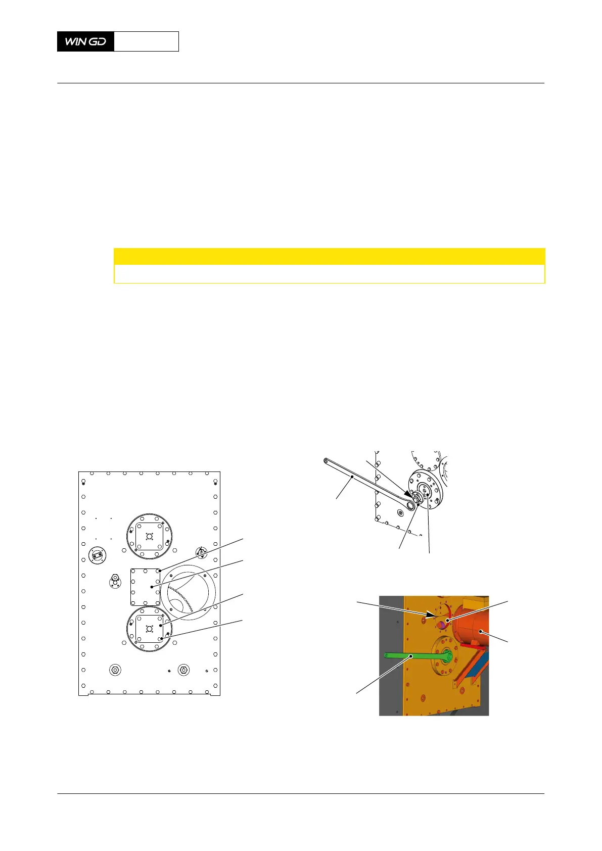
Fig 12-19 Bearing - install
002
ENGINE
SIDE
00582
001
003
005
006
009
008
Molykote D
Loctite 640
002
003
004
005
010
004
007
007
12 Turn the bearing (007) until the taper pin holes are at 90° to the holes in the column
(008).
13 Tighten the nut (006). Make sure that the bearing is in the correct position in the column
(008).
14 Remove the lifting tool (003).
15 Attach the bearing (007) with four of the eight bolts (010). Do not tighten the bolts.
CLOSE UP
• None
X62DF
AA00-7758-00AAA-720A-A
Maintenance Manual Integrated electric balancer - install the bearing (engine side)
Winterthur Gas & Diesel Ltd.
- 711 - Issue 002 2020-10