PROCEDURE
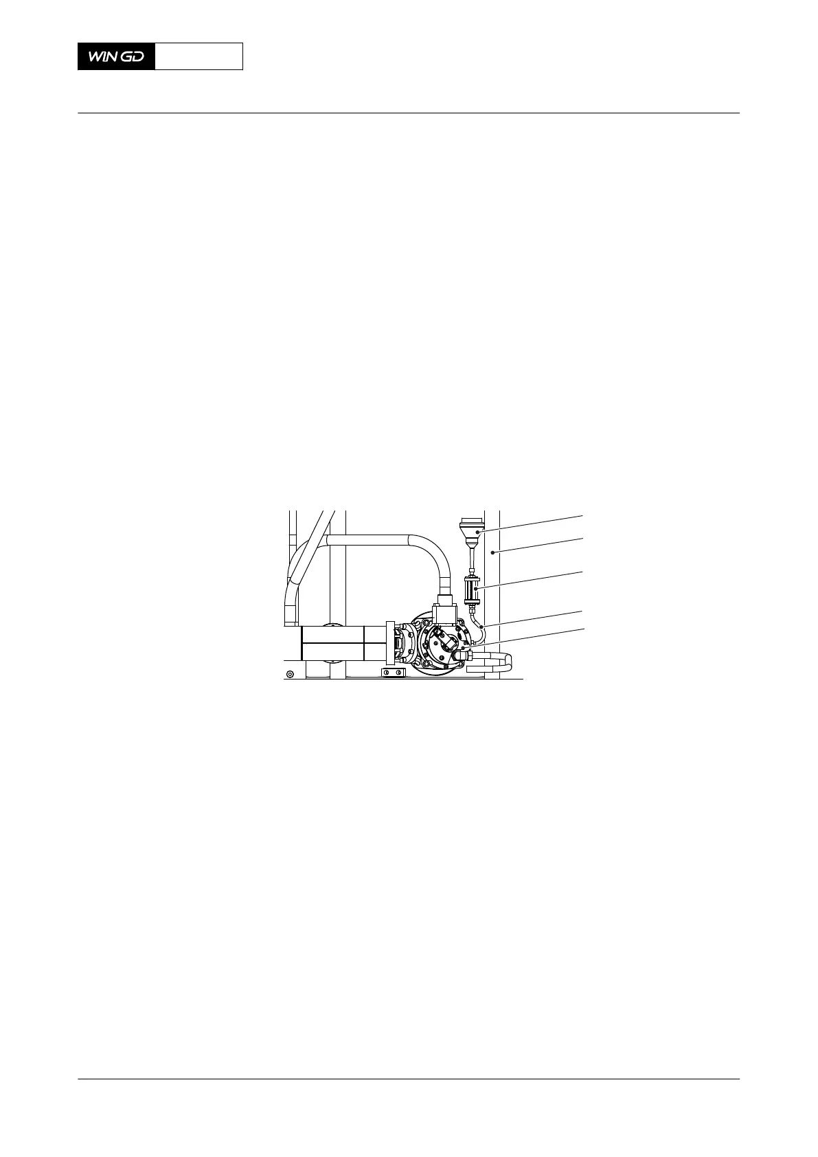
1 Install the measuring tool (003, Figure 7-17) as follows:
1.1 Carefully remove the connection for sealing oil supply on the gas admission
valve (GAV) (005).
1.2 If possible, fill the hose (004) with oil to prevent unwanted air in the system.
1.3 Attach the hose (004) to the connection for sealing oil supply on the GAV.
1.4 Attach the measuring tool (003) to the hose (004).
1.5 Install the funnel (001) to the measuring tool (003).
1.6 Fill the measuring tool (003) with clean lubricating oil (SAE 30) to the top mark.
1.7 Make sure that there is no air in the system.
1.8 Remove the funnel (001).
1.9 Connect the measuring tool (003) to a pressurized air supply at a pressure of
15 bar.
NOTE: You can use the pressure reducing valve 94214B.
Fig 7-17 GAV - do a check of the oil leakage flow
2 Do a check of the oil leakage flow as follows:
2.1 Read the oil level on the scale of the measuring tool (003).
2.2 Start the pressurized air supply.
2.3 Wait 15 minutes.
2.4 Stop the pressurized air supply.
2.5 Read the oil level on the scale of the measuring tool (003).
3 Remove the measuring tool (003) as follows:
3.1 Remove the pressurized air supply.
3.2 Remove the hose (004) from the connection for sealing oil supply.
3.3 Drain the oil into an applicable container.
3.4 Attach the sealing oil supply to the GAV.
4 Make an estimate of the temperature of the GAV.
5 Compare the oil leakage flow with the values given in Table 7-1 - GAV - usual values of
oil leakage flow at 25°C.
X62DF
AA00-2140-00AAA-363A-A
Maintenance Manual Gas admission valve - do a check of the oil leakage flow
Winterthur Gas & Diesel Ltd.
- 203 - Issue 002 2020-10