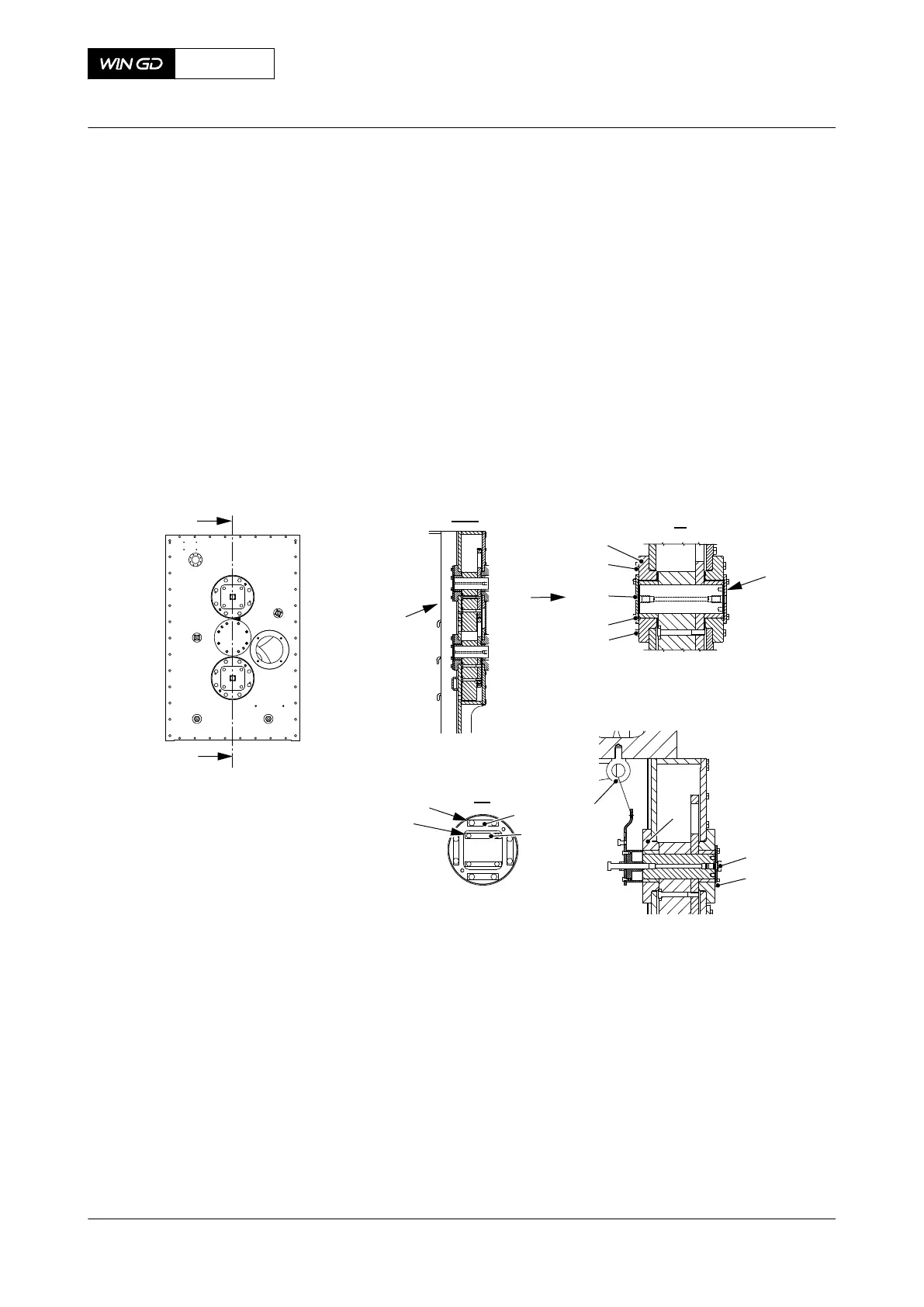
2.1 On the outer side, remove the four screws (004, Figure 12-10) from the bearing
cover (003).
2.2 Remove the bearing cover (003).
2.3 Remove the eight screws (002) from the bearing (001).
Fig 12-10 Outer bearing - remove
I - I
003
00580
001
I
I
OUTER
SIDE
002
004
II
II
ENGINE
SIDE
2.4 Attach the lifting tool (002, Figure 12-11) to the engine room crane (001) and
move it in front of the bearing (006).
2.5 Tighten lightly the screw (004) into the pin (005).
X62DF
AA00-7758-00AAA-520B-A
Maintenance Manual Integrated electric balancer - remove the bearing (outer side)
Winterthur Gas & Diesel Ltd.
- 692 - Issue 002 2020-10