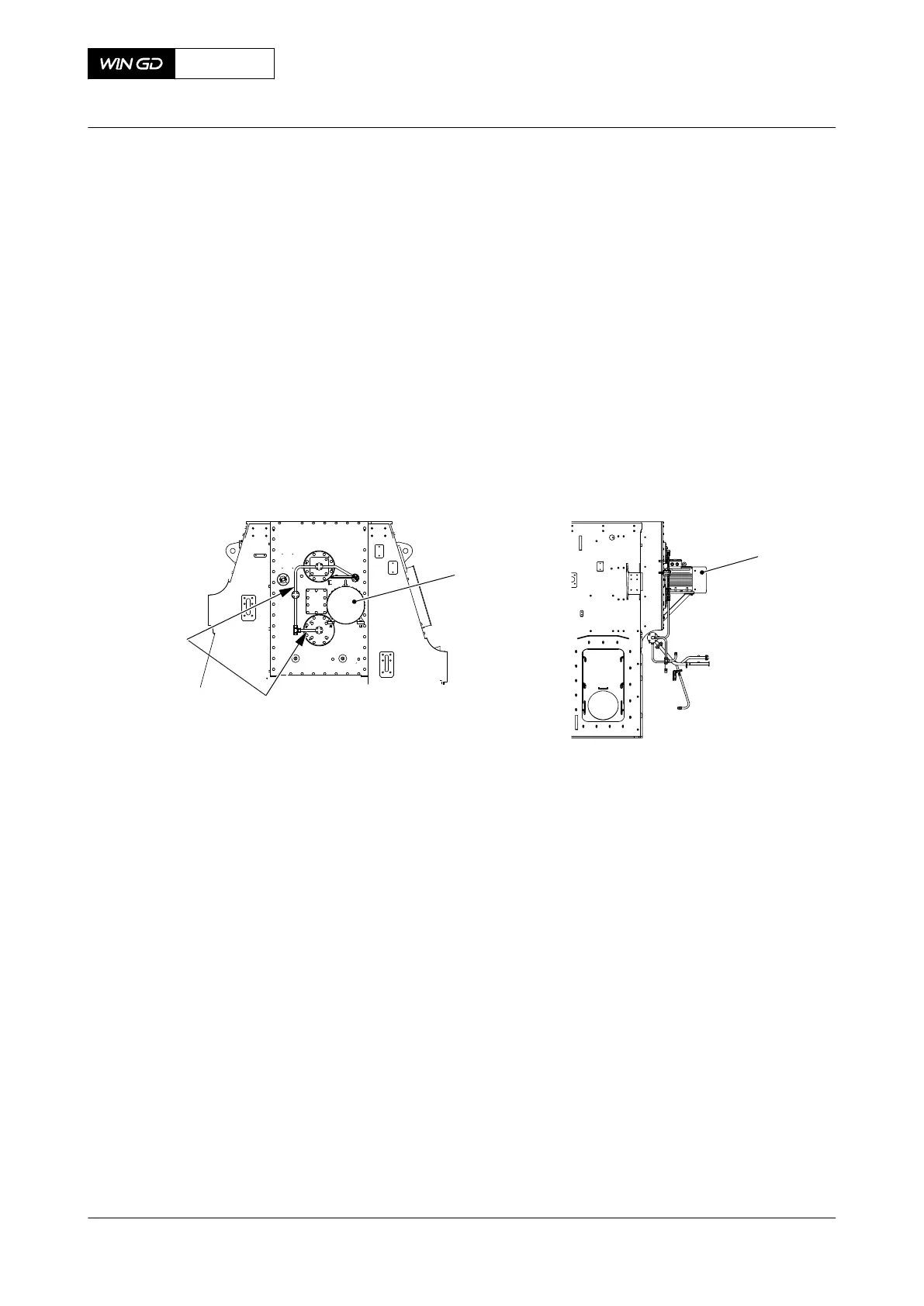
Fig 12-8 Bearing - remove 2
002
00580
001
I
II
003
004
005
007
006
005
006
I
II
III
III
006
002
004
003
001
008
007
M20
002
003
2.10 Move the lifting tool (001) to a position in front of the bearing (007).
2.11 Tighten lightly the screw (004) into the pin (008).
2.12 Turn the nut (003) against the bearing (007) to push the lifting tool (001) against
the pin (008).
2.13 Put the two screws into the two threaded holes (005) in bearing (007).
2.14 Tighten equally the two bolts to push out the bearing (007).
NOTE: The bearing (007) moves on to the lifting tool (001).
2.15 Tighten screw (002) to hold the bearing (007).
2.16 Loosen the nut (003).
2.17 Operate the lever chain hoist to hold the weight of the bearing (007).
2.18 Carefully remove the screw (004).
2.19 Lower the bearing (007) on to an applicable surface.
2.20 Remove the two taper pins (006).
2.21 Remove the lifting tool (001).
2.22 Remove the two bolts (005).
CLOSE UP
• None
X62DF
AA00-7758-00AAA-520A-A
Maintenance Manual Integrated electric balancer - remove the bearing (engine side)
Winterthur Gas & Diesel Ltd.
- 689 - Issue 002 2020-10