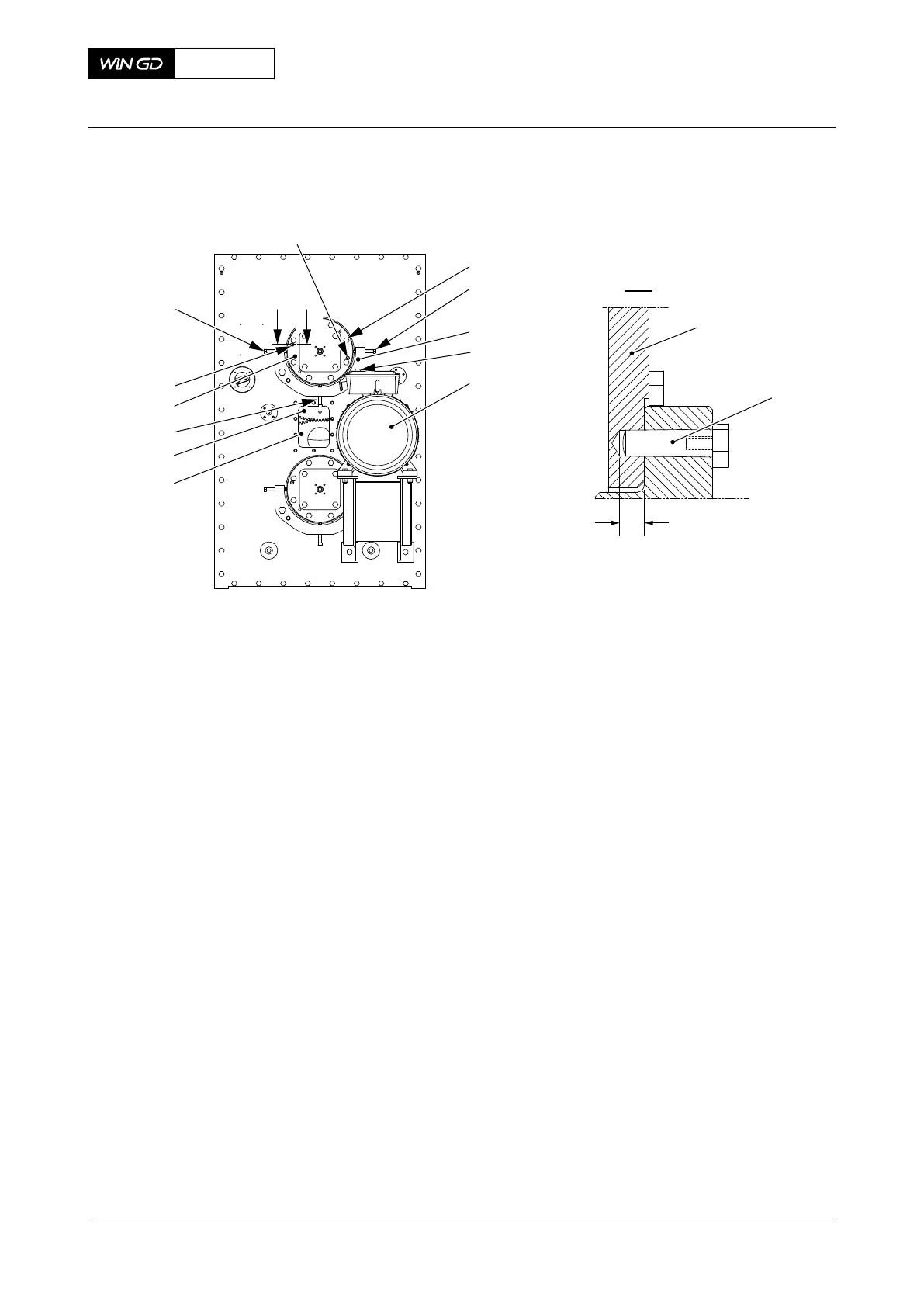
12.2.7 Electric balancer sensor unit - install the proximity sensor
Periodicity
Description
Unscheduled
Duration for performing preliminary requirements 0.0 man-hours
Duration for performing the procedure 0.5 man-hours
Duration for performing the requirements after job completion 0.0 man-hours
Personnel
Description Specialization QTY
Engine crew Intermediate AR
Support equipment
Description Part No. CSN QTY
None
Supplies
Description QTY
None
Spare Parts
Description Part No. CSN QTY
Proximity sensor AR
SAFETY PRECAUTIONS
• None
PRELIMINARY OPERATIONS
• The engine must be stopped.
X62DF
AA00-7762-00AAA-720A-A
Maintenance Manual Electric balancer sensor unit - install the proximity sensor
Winterthur Gas & Diesel Ltd.
- 704 - Issue 002 2020-10