04/2016
4-5
Phaser 4600/4620/4622 Printer Service Manual
REP 1.4
4 Repairs and Adjustments
Revised
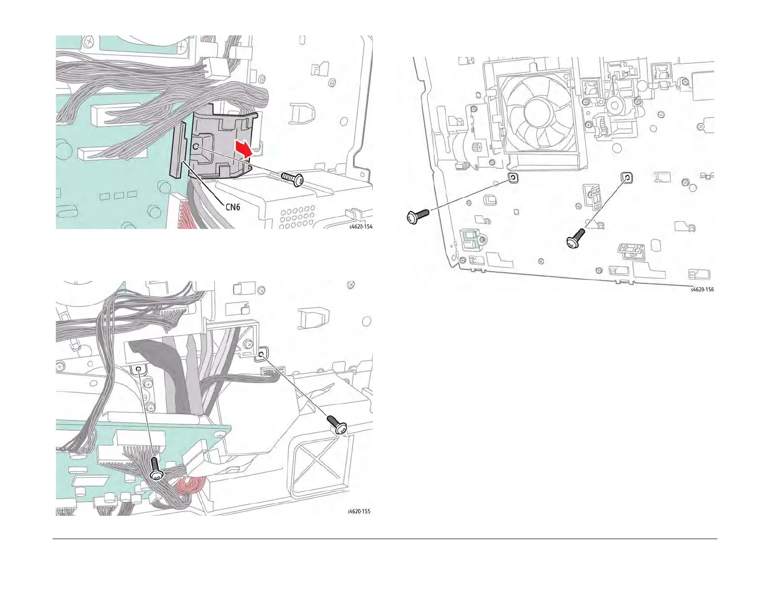
Figure 2 Remove the cable guide
12. Remove 2 screws (metal) that secure the right side of the power supply tray to the chas-
sis, Figure 3.
Figure 3 Remove the right side power supply tray screws
13. Remove 2 screws (metal) that secure the left side of the power supply tray to the chassis,
Figure 4.
Figure 4 Remove the left side power supply tray screws
14. Remove 2 screws (shank, metal) that secure the Fuser connector to the power supply
tray, Figure 5.
15. Disconnect CN3 from the HVPS and move the Fuser harness to the side, Figure 5.