04/2016
6-13
Phaser 4600/4620/4622 Printer Service Manual
GP 12, GP 13
6 General Procedures and Information
Revised
GP 12 How to Check a Solenoid or Clutch
Use this procedure to check a clutch or solenoid.
Initial Actions
WARNING
Switch off the electricity to the machine. Disconnect the power cord from the customer
supply while performing tasks that do not need electricity. Electricity can cause death or
injury. Moving parts can cause injury.
1. For a clutch, check that the shafts, gears, rolls etc., associated with the clutch are free to
rotate, clean and lubricated where applicable.
2. For a solenoid, check that the solenoid is free to actuate and that the mechanisms associ-
ated with the solenoid are free to move.
Procedure
NOTE: The voltages, PJ numbers, pin numbers and PWB names shown are an example only.
Go to the wiring diagram associated with the RAP for the correct information.
NOTE: When a solenoid is energized in diagnostics, movement is seen. When a clutch is ener-
gized in diagnostics, the sound of the clutch action is heard. If possible, run the motor con-
nected to the clutch to confirm when the clutch is energized
1. Enter the dC330 output code for the clutch or solenoid. If the clutch or solenoid does not
energize, continue with step 2.
2. Figure 1, disconnect PJ32, check for +24V at PJ32 pin 2 on the wiring side of the connec-
tor, If the voltage is not correct, trace the faulty component.
3. Reconnect PJ32, enter the dC330 output code for the clutch or solenoid, while measuring
the voltage between CN1 pin 1 and the machine frame. If the voltage does not change
when the code is entered, Install a new PWB.
4. There may be an intermittent fault, perform the actions that follow:
a. Check the wiring. Repair or install new components as necessary.
b. Operate the clutch or solenoid under normal running conditions. If the clutch or sole-
noid operates intermittently or with hesitation, install new parts.
c. Check that the clutch or solenoid has enough drive to operate the mechanism to
which it is attached, if necessary install a new clutch or solenoid.
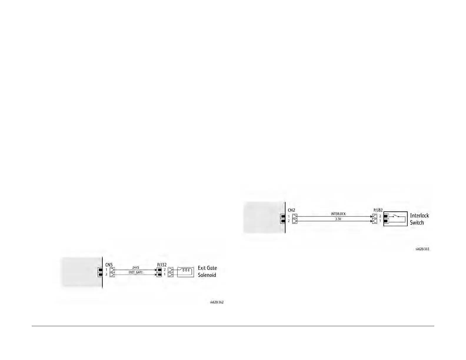
Figure 1 Example Clutch Wiring Diagram
GP 13 How to Check a Switch
Use this procedure to check the operation of a switch.
NOTE: Figure 1 shows an interlock switch actuated by the closing of a door.
Initial Actions
WARNING
Switch off the electricity to the machine. Disconnect the power cord from the customer
supply while performing tasks that do not need electricity. Electricity can cause death or
injury. Moving parts can cause injury.
Manually check that the switch operates. Ensure that the magnet or other actuator has enough
mechanical movement to operate the switch.
NOTE: The voltages, PJ numbers, pin numbers and PWB names shown are an example only.
Go to the wiring diagram associated with the RAP for the correct information.
Procedure
1. Enter diagnostics and check the switch. The switch is operating correctly, check and
adjust the mechanism that actuates the switch
2. Refer to Figure 1, then disconnect T072.
3. +5V is available between pin 1 and pin 2 on the wiring side of the connector.
4. +5V is available at PJ5 between pins 3 and 4 on the PWB.
5. Check the supply voltage. If +5V is available, install a new PWB.
6. Check the wiring between PJ5 and T072. Repair or install new parts as necessary.
7. Install a new switch.
Figure 1 Example Switch Wiring Diagram