04/2016
4-118
Phaser 4600/4620/4622 Printer Service Manual
REP 10.32
Revised
4 Repairs and Adjustments
REP 10.32 Exit Drive Assembly
Parts List on PL 10.30 Item 23
Removal
WARNING
Switch off the electricity to the machine. Disconnect the power cord from the customer
supply while performing tasks that do not need electricity. Electricity can cause death or
injury. Moving parts can cause injury.
1. Remove the Duplex Unit, REP 10.1.
2. Remove the IP Board Cover, REP 28.1.
3. Remove the Right Cover, REP 28.2.
4. Remove the Waste Toner Cartridge.
5. Remove the Left Cover, REP 28.3.
6. Remove the IP Board Cage, REP 3.5.
7. Remove the Top Cover, REP 28.5.
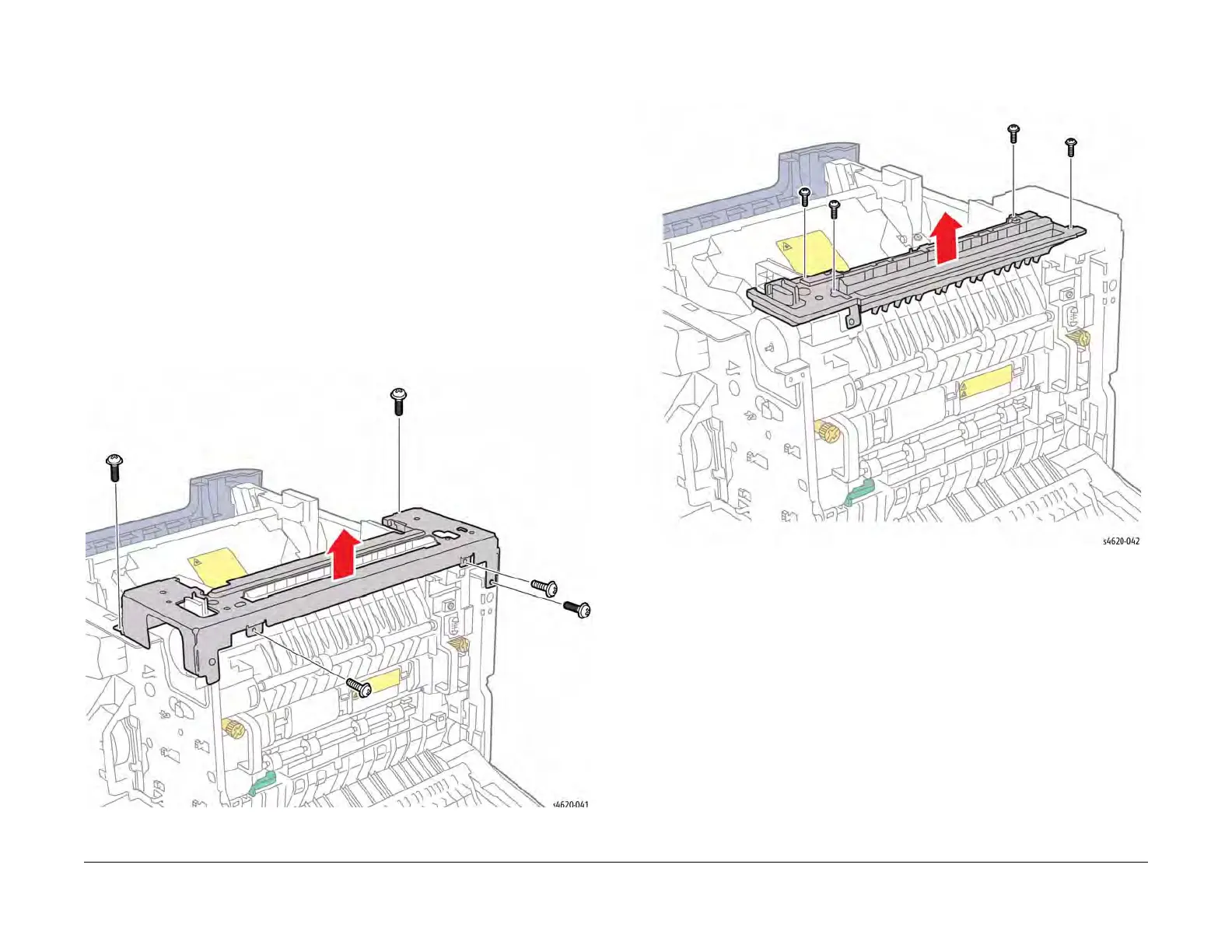
8. Remove 5 screws (2 plastic, 3 metal) that secure the rear support bracket to the chassis.
9. Lift the bracket and rest on the printer chassis, Figure 1.
Figure 1 Remove the rear support bracket
10. Remove 4 screws (plastic) that secure the Exit Chute to the chassis.
11. Lift the chute and rest on the support bracket, Figure 2.
Figure 2 Remove the Exit Chute screws
12. Remove 4 screws (metal) that secure the Exit Drive Assembly to the chassis.
13. Disconnect P/J40 to remove the Exit Drive Assembly, Figure 3.